 en
en English
 Русский
 España
 عرب .
عرب .

If you need any help, please feel free to contact us
inquire
Capacitive Level Switches: How They Work, Selection & Installation Guide
How a Capacitive Level Switch Works
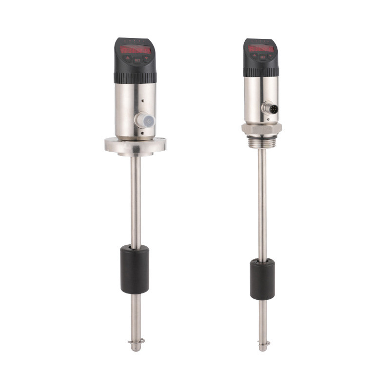
A capacitive level switch detects the presence or absence of material at a fixed point in a tank, silo, or pipeline by measuring changes in electrical capacitance. The physics are straightforward: capacitance — the ability of a system to store electrical charge — depends on the area of two conductive surfaces, the distance between them, and the dielectric constant of whatever material sits between them. When the medium in a vessel rises to cover the sensing probe, the dielectric between the probe and the tank wall changes from air (dielectric constant ≈ 1) to liquid or bulk solid (dielectric constant typically 2–80). That shift in capacitance is detected by integrated electronics and triggers an output switch signal.
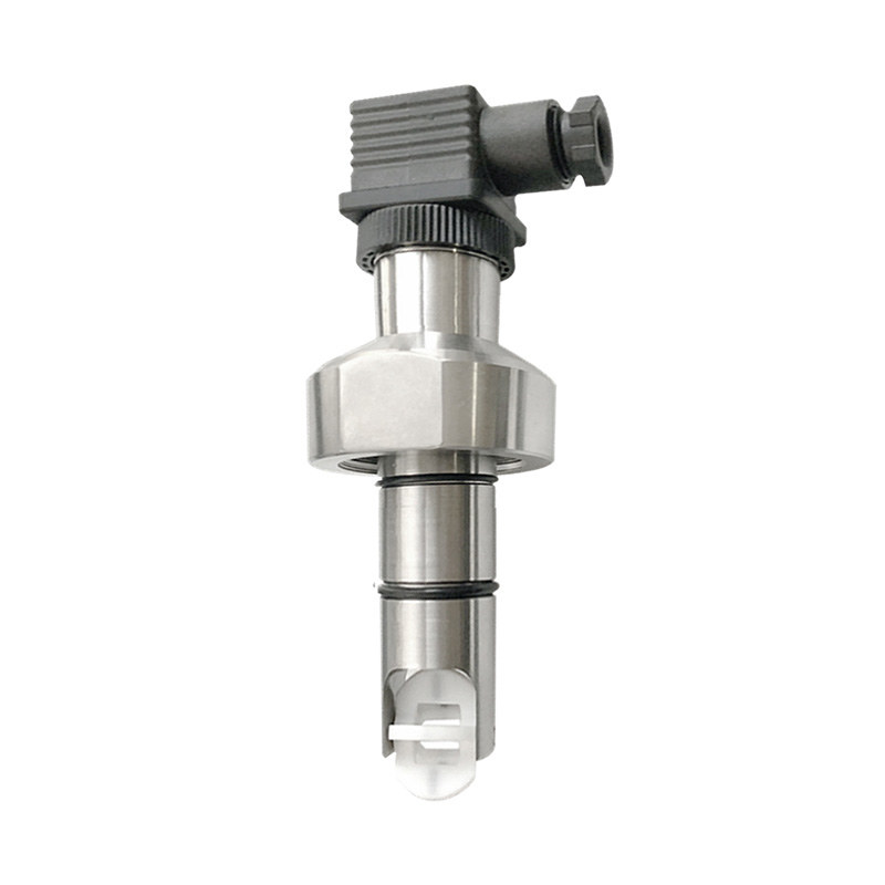
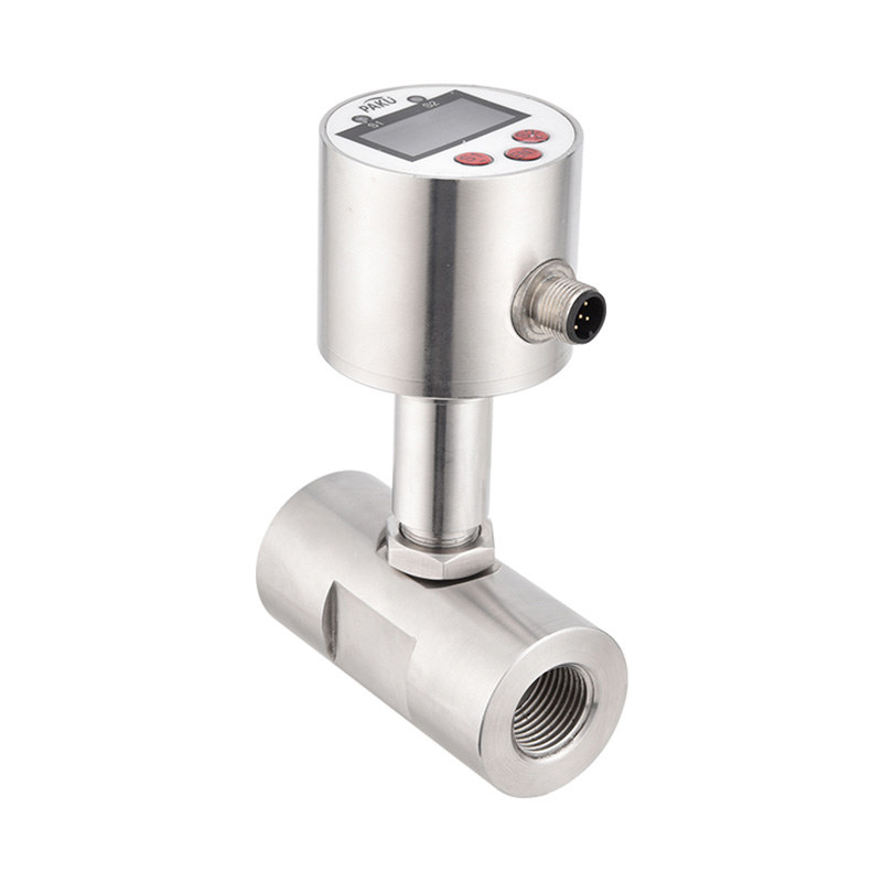
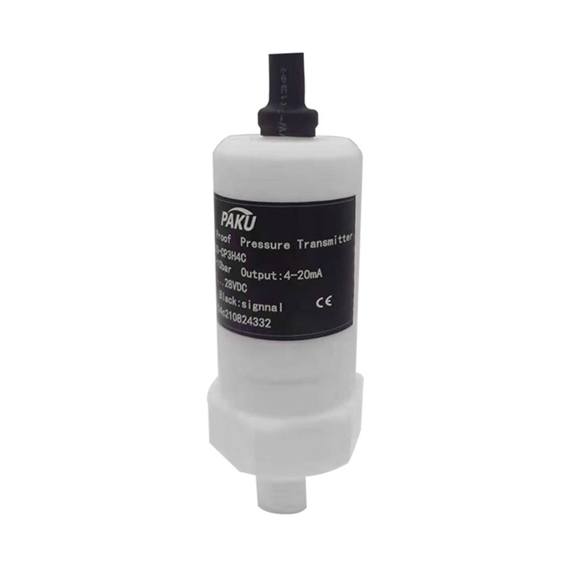
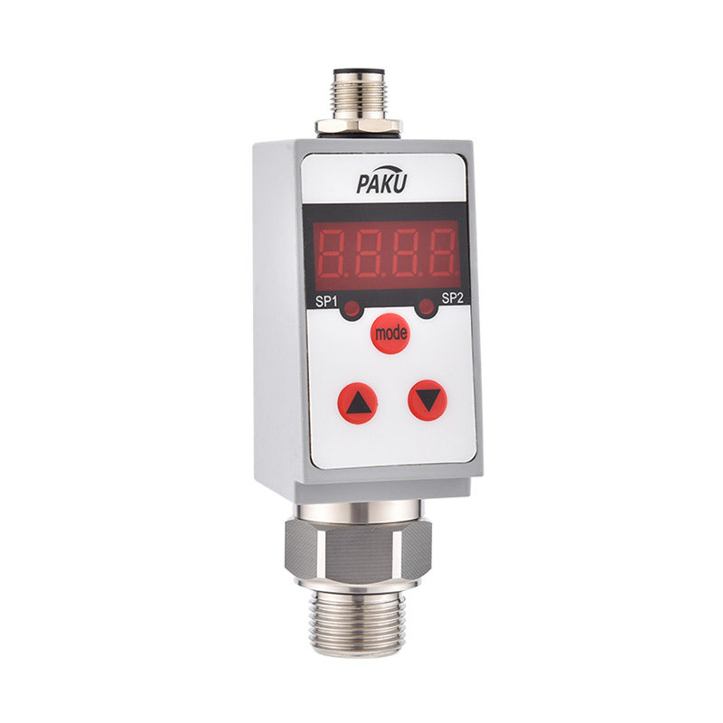
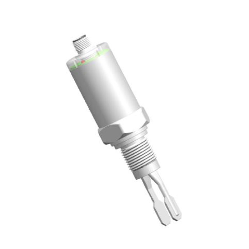
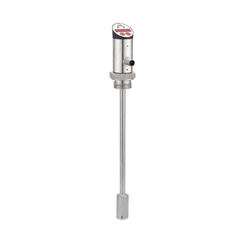
The probe itself forms one electrode of the capacitor. In a metal tank, the tank wall acts as the second electrode. In a non-conductive vessel — plastic, fiberglass, or coated steel — a separate reference electrode or ground rod is required to complete the capacitive circuit. The electronics continuously compare measured capacitance against a threshold set during commissioning: when the reading crosses that threshold, the switch output changes state, triggering a pump, valve, or alarm. For a compact solution built on this principle, see the miniature capacitive level switch LF100D — a fully insulated probe design suited for both liquid and solid media detection.
Two Operating Modes: Conductive and Non-Conductive Media
Capacitive level switches handle both conductive and non-conductive media, but the mechanism differs between the two, and this distinction drives several selection and configuration decisions.
For conductive liquids — water, aqueous solutions, acids, bases, and most process chemicals — the liquid itself forms the second electrode of the capacitor. The probe is coated with an insulating layer (PTFE, PFA, or ceramic) to prevent the conductive liquid from short-circuiting the sensing circuit. As the conductive medium rises to cover the probe, a large and sharply defined capacitance change occurs, giving a clean, reliable switching point with minimal sensitivity adjustment required. Media with electrical conductivity above 100 µS/cm generally require no additional calibration at installation.
For non-conductive media — oils, hydrocarbons, dry powders, plastics, and many organic solvents — the capacitance change per unit level is smaller and depends entirely on the dielectric constant (ε) of the material. Liquids like fuel oil (ε ≈ 2–3) and dry powders generate a weaker signal than water (ε ≈ 80). Switches for non-conductive service require higher sensitivity settings, longer probe lengths (minimum 500 mm is a common guideline for materials with ε < 3), and careful calibration against the actual process material. An RF admittance variant — which measures both capacitance and conductance — provides superior compensation for coating and buildup in these applications.
Advantages Over Mechanical Level Switches
The case for capacitive technology rests largely on reliability in conditions where mechanical switches fail routinely. Float switches hang up on scale deposits or product buildup. Paddle-type switches break when struck by agitators or material surge. Vibrating fork switches can be dampened by viscous, sticky media. Capacitive switches have none of these failure modes because there are no moving parts — only a probe and electronics.
Key operational advantages include:
- No moving parts: Eliminates wear-related failures and significantly extends service life in corrosive or abrasive service.
- Broad media compatibility: Handles liquids, slurries, pastes, powders, granules, and bulk solids with a single technology platform, adjusting only sensitivity settings between applications.
- High-temperature and high-pressure capability: Properly specified units can operate at temperatures up to 200°C and pressures up to 2 MPa — conditions that would destroy most float or paddle switches.
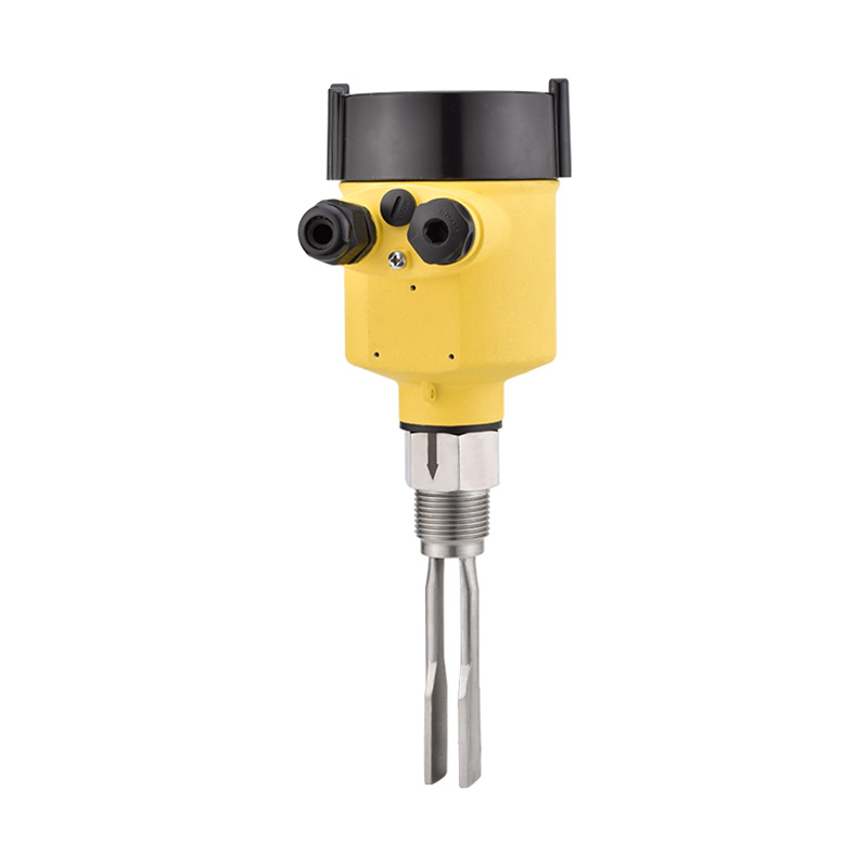
- Compact installation footprint: A single threaded fitting or flange nozzle is all that's required. Compared to the tuning fork level switch — which is also a no-moving-parts technology but is limited to certain media types — capacitive switches offer broader material range at lower insertion depth requirements.
- Easy output integration: Relay, PNP/NPN transistor, and 4–20 mA outputs allow direct connection to PLCs, DCS systems, or simple control relays without signal conditioning hardware.
Industrial Applications
Capacitive level switches are found across virtually every process industry, precisely because they are insensitive to the fluid properties that disqualify other technologies. The same probe design that monitors demineralized water in a pharmaceutical tank can be recalibrated for a cement silo or a fuel storage vessel.
Common application categories include: high-level overfill alarms in chemical storage tanks; low-level dry-run protection for pumps handling corrosive media; bin and hopper level control for powders, granules, and plastics in food, pharmaceutical, and plastics manufacturing; sludge level detection in wastewater clarifiers and thickeners; fuel and lubricant level monitoring in hydraulic systems and machine tools; and interface detection between two immiscible liquids — such as oil over water — where the dielectric contrast between the two phases is sufficient for reliable discrimination.
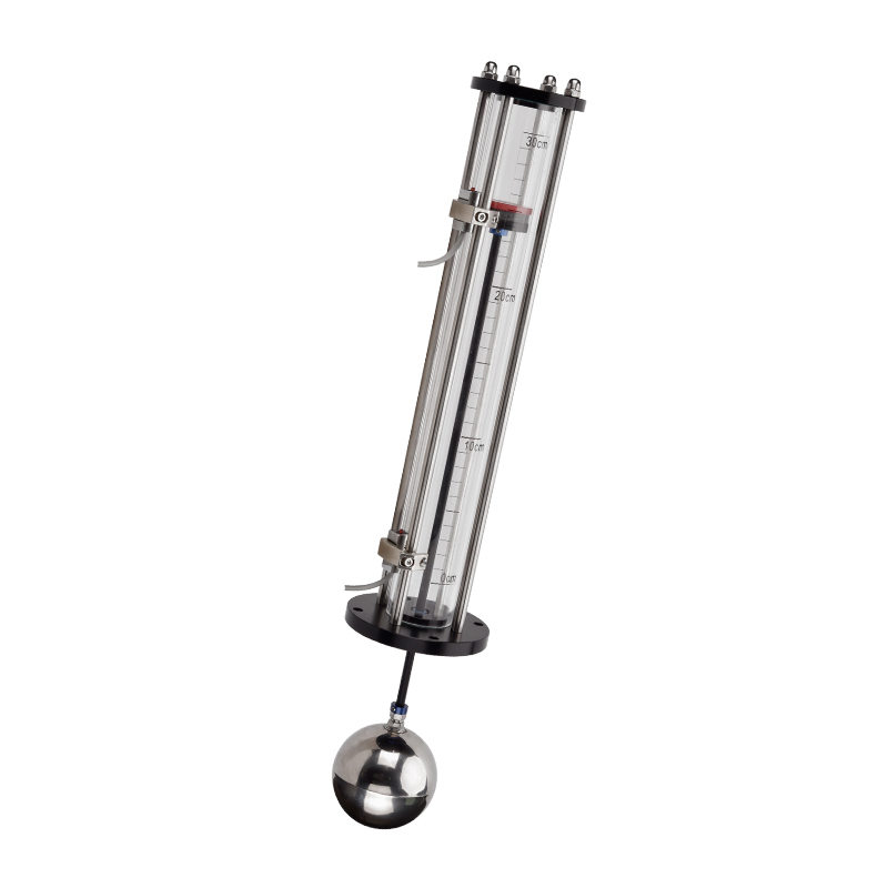
In hazardous area installations, capacitive switches are available with ATEX, IECEx, and NEC Class I/Division 2 certifications for use in flammable or explosive atmospheres. For continuous level measurement rather than point detection, an RF capacitance level transmitter extending the full height of the vessel provides a proportional 4–20 mA output for continuous inventory monitoring.
Selection Criteria
Getting the right capacitive level switch requires matching five parameters to the application before looking at product catalogs.
Dielectric constant of the process medium determines probe length and sensitivity. Materials with ε > 10 are straightforward. Materials with ε between 2 and 5 (oils, hydrocarbons, dry organics) demand higher-sensitivity variants, and materials with ε below 2 may not be detectable without RF admittance technology.
Process temperature and pressure govern the probe material, seal material, and housing rating. Standard units cover up to 100°C; high-temperature versions handle up to 200°C. Confirm that PTFE, PFA, or ceramic insulation is rated for both the thermal and chemical environment.
Media conductivity and coating tendency — for media that coat the probe (sticky pastes, crystallizing solutions, viscous polymers), choose a version with an active coating compensation circuit or RF admittance technology. Standard capacitive switches will false-trigger on buildup if the coating has a substantially different dielectric constant than the background (air).
Tank material and geometry — for non-metallic tanks, confirm that an auxiliary ground electrode is included or that the switch has a coaxial probe design that provides its own reference electrode independently of the tank wall.
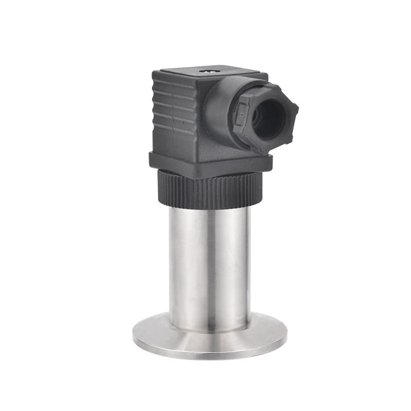
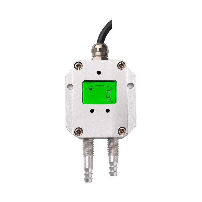
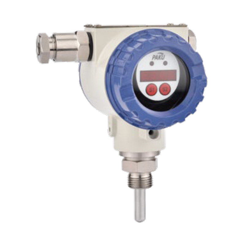
Output and connection standard — relay output suits simple pump-and-alarm control; 4–20 mA or IO-Link suits systems requiring diagnostics, remote calibration, or integration with field bus networks. For an option combining both level sensing and pressure-based level measurement in a single instrument, the capacitive pressure and liquid level transmitter PN52C delivers hydrostatic level output with capacitive sensing technology.
Installation Best Practices
Correct mounting eliminates the majority of false-alarm complaints associated with capacitive level switches. Follow these guidelines to ensure reliable long-term operation.
Mount the probe on the side wall of the vessel at the desired switching height, not near the fill inlet. Direct material impact during filling can momentarily cover the probe and cause spurious signals — position the switch at least 200–300 mm away from any inlet nozzle. For top-mounted installations, maintain a minimum clearance of 200 mm between the probe tip and the inner tank wall to prevent proximity effects from the wall capacitance influencing the reading.
Ensure proper grounding. For metal tanks, the tank itself provides the ground reference, but verify that a low-resistance electrical connection exists between the probe housing and the tank. For plastic or coated tanks, use a switch with a built-in reference electrode or install a separate ground rod in the vessel. In high-power electrical environments — near large motors, VFDs, or welding equipment — specify 24 VDC-powered models and run signal cables in shielded conduit to minimize electromagnetic interference.
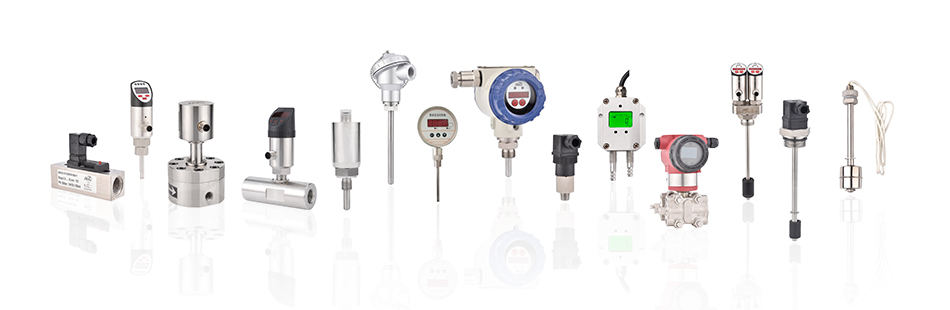
After installation, calibrate with the vessel empty (air reference) and then filled to the switching point with the actual process medium. Do not calibrate using a substitute fluid, as the dielectric constant difference between the calibration medium and the process medium will produce a shifted switching point. Revisit calibration any time the process chemistry changes. For a full overview of liquid level switch technologies available for different process requirements, the product series covers float, tuning fork, electronic, and capacitive variants across the same installation form factors.
information
 [email protected]
![]() +86-13386111894 / +86-021-37566990
+86-13386111894 / +86-021-37566990
![]() B-4th Floor, Lane 1313, Nanting Road, Nanqiao Town, Fengxian District, Shanghai, China
B-4th Floor, Lane 1313, Nanting Road, Nanqiao Town, Fengxian District, Shanghai, China

Product Links