 en
en English
 Русский
 España
 عرب .
عرب .

If you need any help, please feel free to contact us
inquire
How a Pressure Sensor Measures Water Level: Principles, Benefits & Selection Guide
A column of water 10 meters deep exerts a predictable, calculable force on anything at its base. That simple physical fact is what makes pressure-based water level measurement one of the most reliable approaches in industrial and environmental monitoring today. Unlike optical or float-based methods, a pressure sensor doesn't care about foam, turbulence, or condensation — it just reads the force of the water above it and translates that into a level reading with high repeatability.
This article breaks down how that translation works, where the method excels over alternatives, and what to look for when specifying a sensor for your application.
How Pressure Sensors Measure Water Level
The operating principle is hydrostatic pressure: the pressure at any point in a static liquid is proportional to the height of liquid above it. The governing equation is P = ρgh, where P is the measured pressure, ρ is the fluid density, g is gravitational acceleration, and h is the depth. Rearranged to solve for depth: h = P / (ρg). Because water density and gravity are effectively constant in most applications, the sensor's pressure output maps directly and linearly to level.
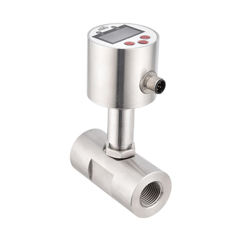
In practice, a pressure sensor is installed at a fixed reference point — typically the bottom of a tank or at a known depth in a well. As the water level rises, the hydrostatic head increases and the sensor output increases proportionally. Signal outputs are commonly 4–20 mA or 0–10 V DC, both of which integrate cleanly with PLCs, data loggers, and SCADA systems.
One detail worth noting: most installations use gauge pressure sensors rather than absolute pressure sensors. A gauge sensor measures pressure relative to local atmospheric pressure, which means fluctuations in barometric pressure cancel out automatically. Vented submersible units accomplish this through a small atmospheric vent tube running along the cable — a straightforward but important design feature for outdoor and long-term deployments. For submersible liquid level transmitters designed for continuous depth monitoring, this venting is typically built into the cable assembly.
Key Advantages Over Other Level Sensing Methods
Pressure-based level measurement is far from the only option, but it consistently outperforms alternatives in submerged or turbulent environments. Here's how it stacks up against the most common alternatives:
| Method | Principle | Strengths | Limitations |
|---|---|---|---|
| Pressure sensor (hydrostatic) | P = ρgh | High accuracy, no moving parts, works in turbulent/foamy media | Requires known fluid density; sensor must be submerged or at tank bottom |
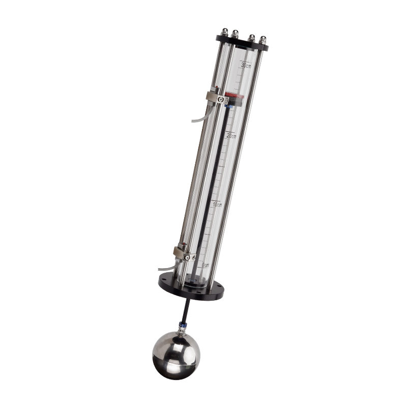
| Float / displacer | Buoyancy | Simple, low cost | Moving parts wear out; affected by viscosity and agitation |
| Ultrasonic | Time-of-flight (air) | Non-contact; no wetted parts | Foam, vapor, and steep angles cause signal loss |
| Radar | Microwave reflection | Unaffected by vapor; high accuracy | Higher cost; overkill for simple water level tasks |
| Capacitive | Dielectric change | Good for small tanks, clean media | Coating and fouling alter readings; limited range |
For water specifically — which has a well-known, stable density — pressure sensors deliver accuracy and long-term stability that is difficult to match at equivalent cost. The absence of moving parts also translates directly to lower maintenance intervals in demanding field conditions.
Common Application Scenarios
The versatility of hydrostatic pressure measurement means the same fundamental technology appears across a wide range of industries and environments.
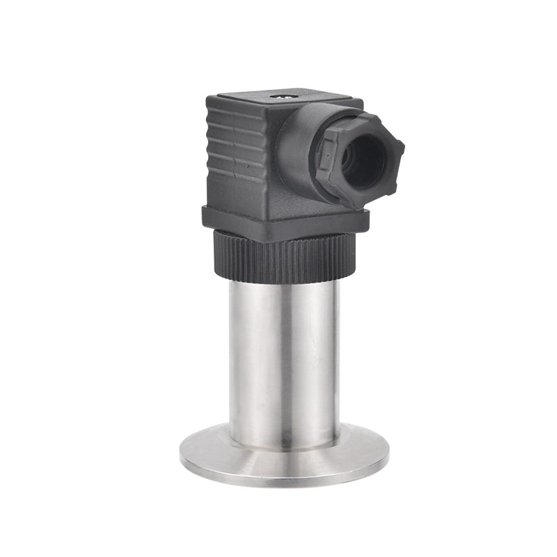
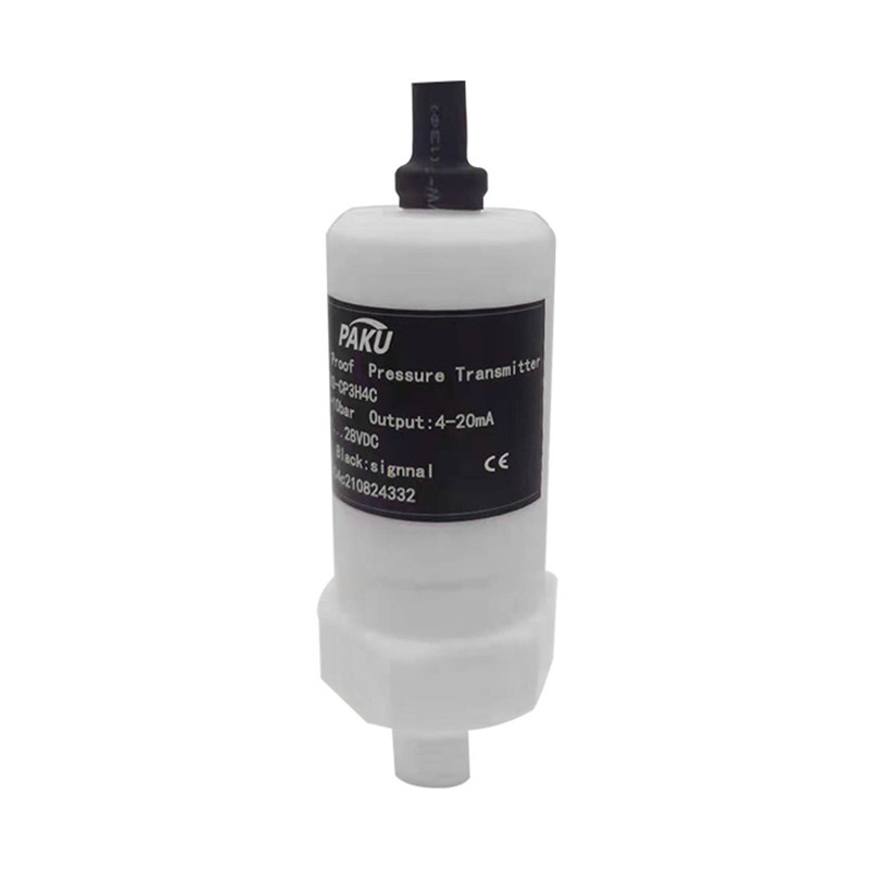
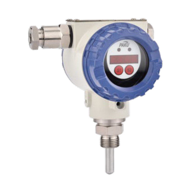
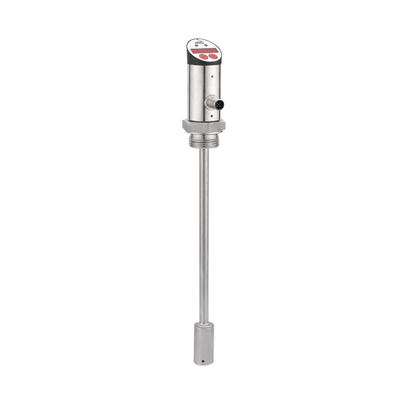
Above-ground storage tanks: Sensor mounted at the tank floor continuously reports fill level to a central controller. Level changes from supply or draw-off are captured in real time. Hydrostatic liquid level sensors for tanks and open channels are purpose-built for exactly these installations, with compact submersible housings suited to confined tank geometries.
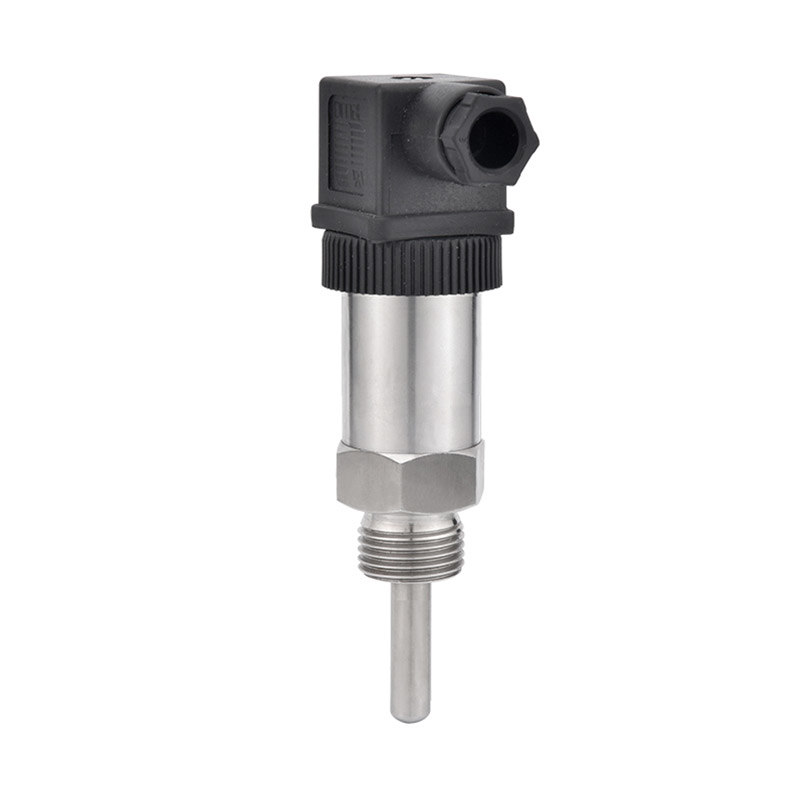
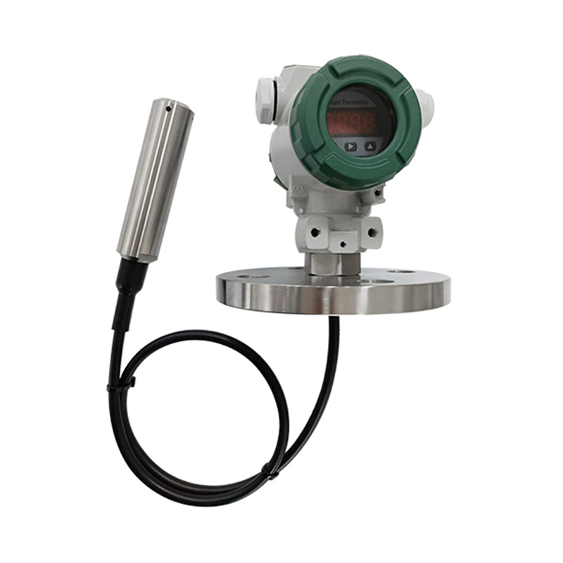
Groundwater wells and boreholes: A submersible pressure transducer lowered into a well measures the static and dynamic water table. This data is critical for aquifer management, irrigation scheduling, and environmental compliance monitoring. Accuracy requirements for groundwater applications are stringent — authoritative guidance from the USGS standards for submersible pressure transducers in water-resources investigations recommends system accuracy of ±0.01 ft for most hydrological projects.
Rivers, canals, and open channels: Flood warning systems and irrigation networks rely on continuous stage readings. Submerged sensors placed at fixed datum points transmit water height to remote monitoring platforms, often via cellular or satellite telemetry.
Municipal water supply and wastewater treatment: From elevated reservoirs to settling tanks, pressure-based level sensing drives pump control, overflow protection, and process automation across the water treatment chain.
How to Select the Right Pressure Sensor for Water Level
Getting the specification right comes down to five parameters.
Measurement range: Match the sensor's full-scale pressure range to the maximum expected water depth. A sensor rated for 0–10 m H₂O on a 2-meter tank runs most of its life in the bottom 20% of its range — accuracy degrades. Conversely, undersizing risks overrange damage. Select a range where normal operating depth sits between 40% and 80% of full scale.
Accuracy and long-term stability: For process control, ±0.5% FS is typically adequate. For environmental data collection or custody transfer applications, look for ±0.1% FS or better, combined with a low annual drift specification.
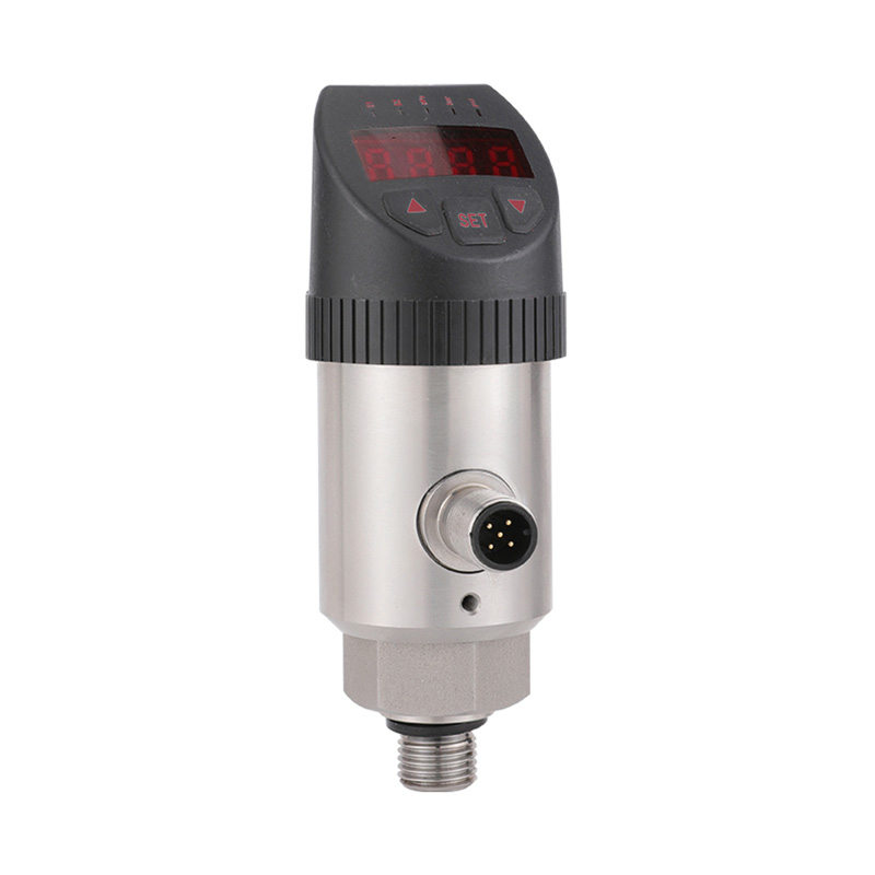
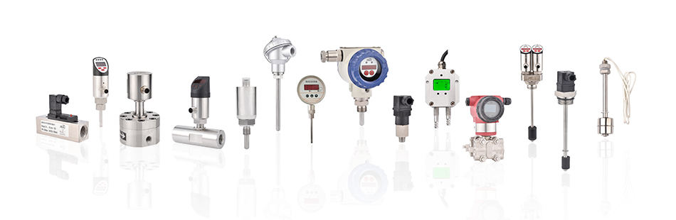
Output signal and protocol: The 4–20 mA loop is standard for industrial installations owing to its noise immunity over long cable runs. For digitally-integrated systems or where multiple sensors share a bus, RS-485 or HART protocol variants offer added diagnostic capability. Browse the range of pressure sensors across a wide measurement range to match output signal to your controller requirements.
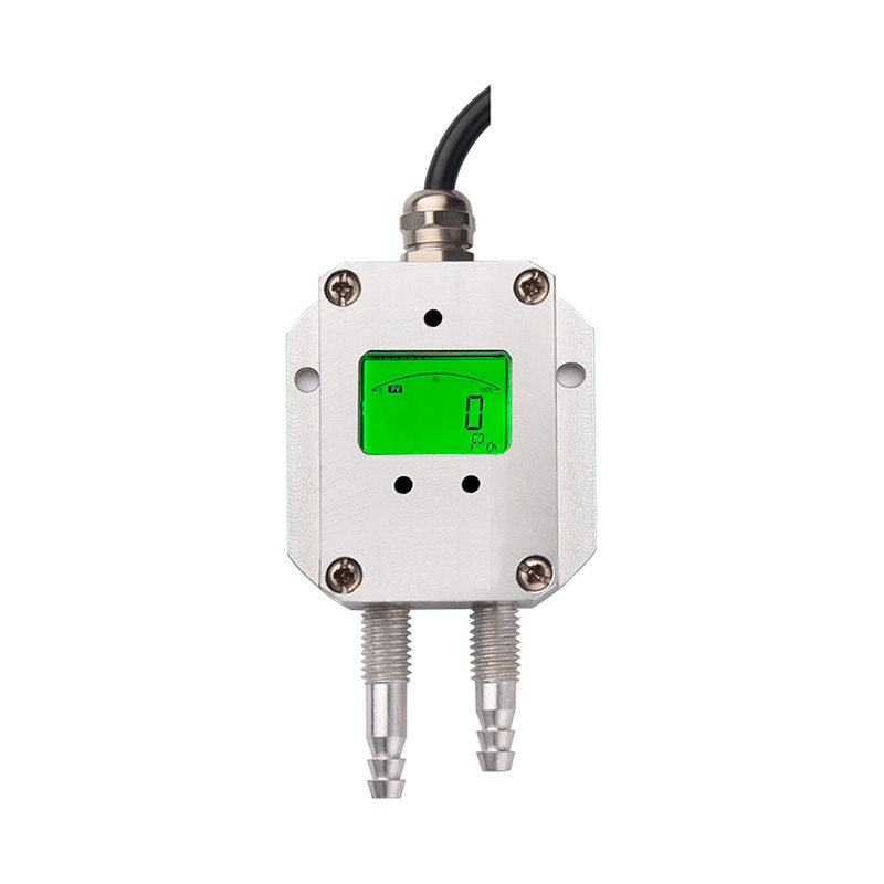
Low-range and differential applications: Shallow sumps, drains, or overhead tanks with limited head may produce very small pressure differentials. Standard sensors lose resolution at the low end of their range. Micro differential pressure transmitters for low-range applications are optimized for precisely these scenarios, maintaining accuracy at signal levels that would overwhelm a general-purpose unit.
Materials and ingress protection: Sensors in outdoor wells or wastewater environments must be rated IP68 as a minimum. Wetted materials should be compatible with the specific water chemistry — stainless steel suffices for clean water; PTFE-lined or ceramic sensing elements are preferred for treated or chemically dosed water.
Installation Tips for Accurate Readings
Even a well-specified sensor will underperform if installed incorrectly. A few common-sense practices eliminate most field accuracy problems.
- Fix the sensor position firmly. Any movement in a submersible sensor changes the reference depth and introduces noise into the level reading. In wells, use a dedicated mounting bracket or cable strain relief at the wellhead. In tanks, anchor the cable at the top of the tank so the sensor hangs at a consistent depth.
- Keep the vent tube clear. For gauge-type sensors with an atmospheric vent cable, the vent path must remain unobstructed and free of moisture ingress. A blocked vent creates a sealed air pocket that shifts the zero reference as temperature changes.
- Allow thermal stabilization after installation. Sensor electronics produce a small amount of heat. Readings taken immediately after power-on can drift by 0.1–0.3% FS. Allow 15–30 minutes of stabilization before recording baseline data.
- Avoid turbulent inflow zones. Never install a level sensor directly below a fill inlet or pump discharge. Turbulence creates dynamic pressure pulses that corrupt the static hydrostatic reading. Position the sensor at least 300 mm horizontally from any inlet.
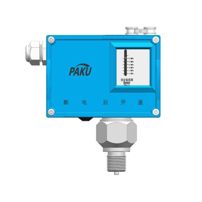
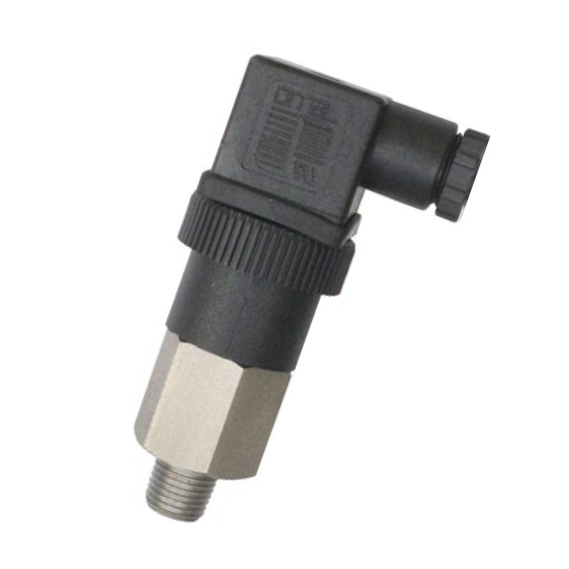
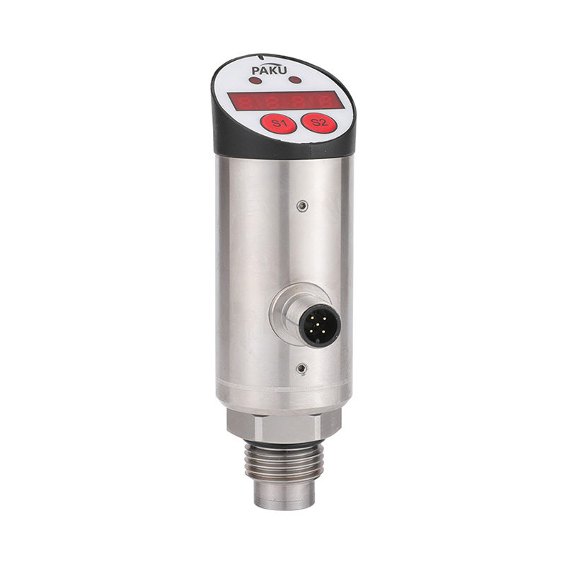
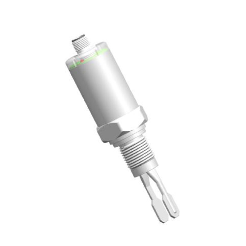
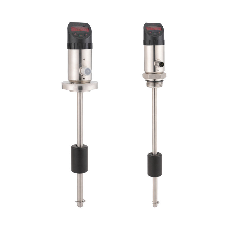
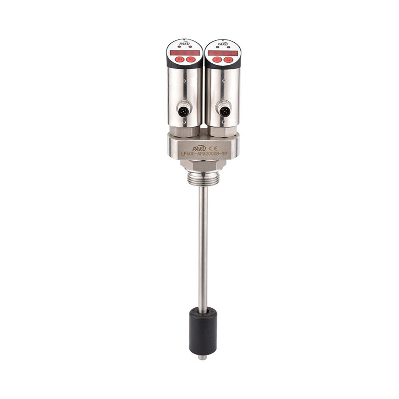
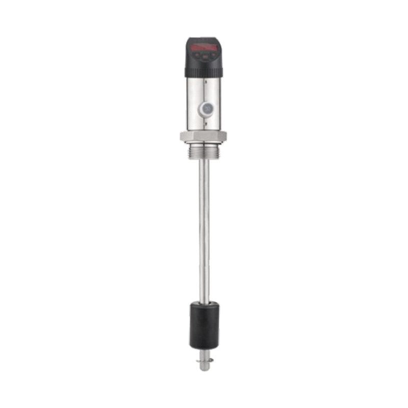
- Consider pairing with alarm switches. For applications where level crossing a threshold triggers an action — pump start, overflow alarm, or low-level shutoff — pairing the continuous transmitter with liquid level switches for high/low alarm control provides a reliable, independent secondary trigger that does not depend on the analog signal chain.
A pressure sensor measuring water level is one of the more forgiving instrument choices in industrial metrology — stable, drift-resistant, and mechanically simple. Getting the range, materials, and installation geometry right from the outset means years of accurate, low-maintenance data collection with minimal intervention.
information
 [email protected]
![]() +86-13386111894 / +86-021-37566990
+86-13386111894 / +86-021-37566990
![]() B-4th Floor, Lane 1313, Nanting Road, Nanqiao Town, Fengxian District, Shanghai, China
B-4th Floor, Lane 1313, Nanting Road, Nanqiao Town, Fengxian District, Shanghai, China

Product Links