 en
en English
 Русский
 España
 عرب .
عرب .

If you need any help, please feel free to contact us
inquire
If you have any further questions, please call +86-021-37566990 or fill out the inquiry form.
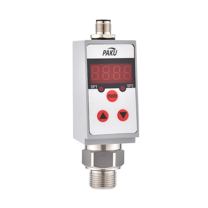
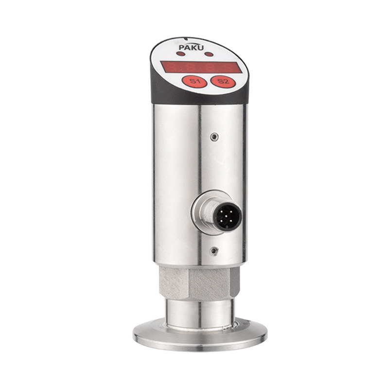
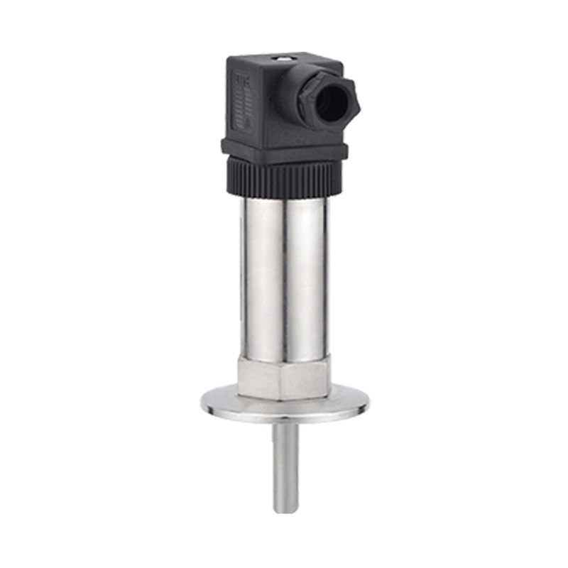
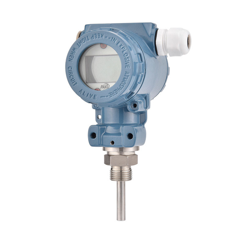
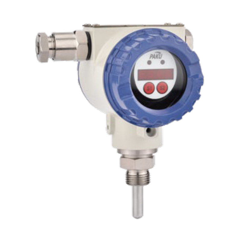
Get coupons PDF DownloadCapacitive pressure (liquid level) transmitter-PN52C
Product introduction
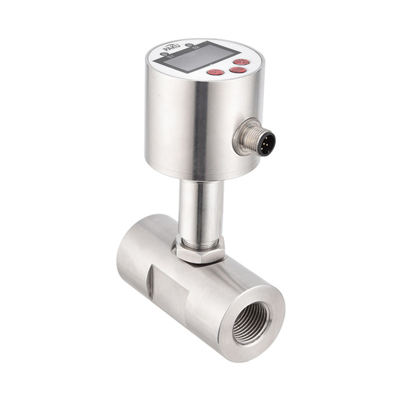
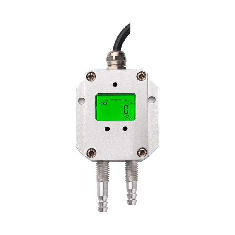
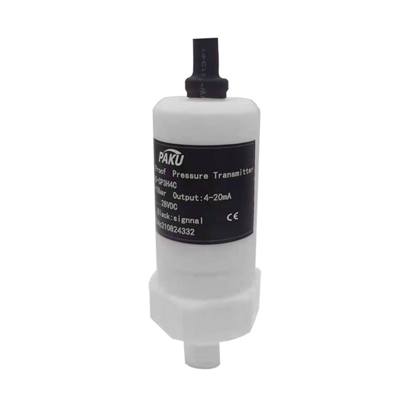
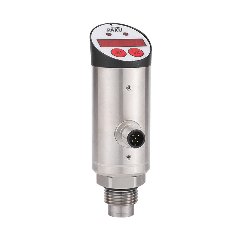
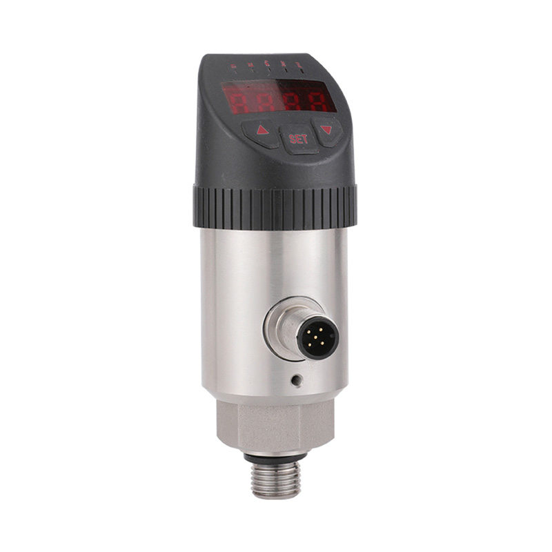
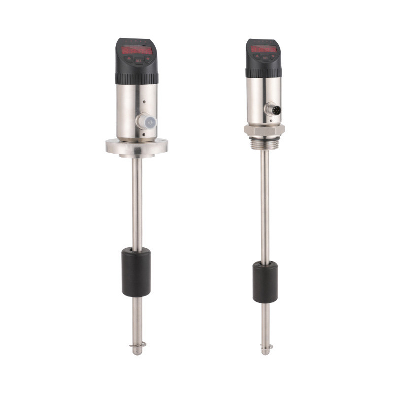
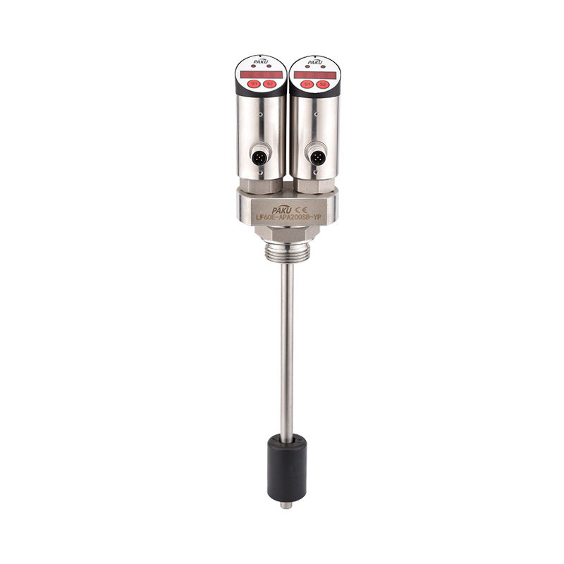
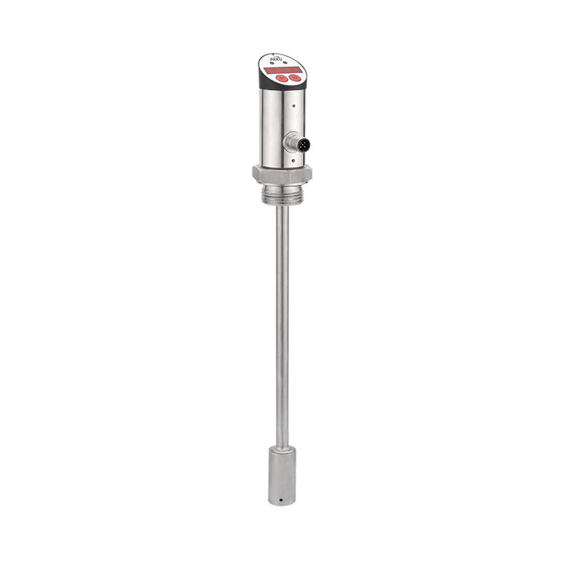
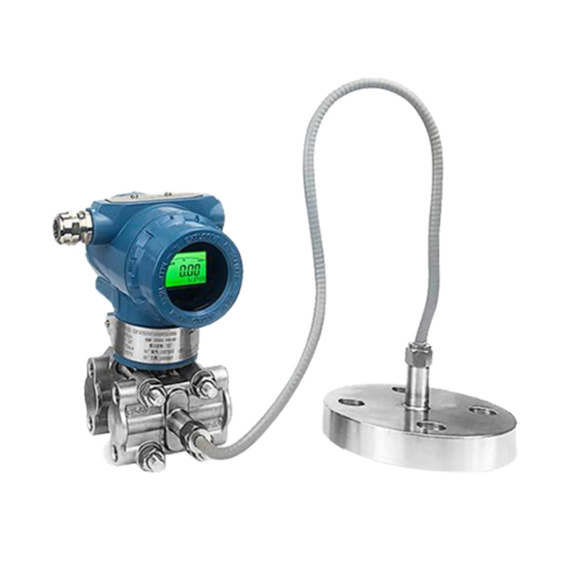
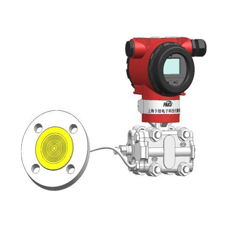
PN52C series pressure (level) transmitters use capacitive pressure core working, high and low pressure side of the isolation diaphragm and filling fluid to transfer the process pressure to the filling fluid, and then the filling fluid to transfer the pressure to the sensor center of the sensing diaphragm. The sensing diaphragm is a tensified elastic element whose displacement varies with the pressure applied (for a gauge transducer, atmospheric pressure is applied as on the low pressure side of the sensing diaphragm). The adiabatic pressure transmitter maintains a reference pressure at all times on the low pressure side. The maximum displacement of the sensing diaphragm is 0.1 mm, and the displacement is proportional to the pressure. The capacitive plates on both sides detect the position of the sensing diaphragm. The capacitance difference between the sensing diaphragm and the capacitor plate is converted to the corresponding current or digital HART output signal.
Technical Specification
Main Features
Application
Range Of Code
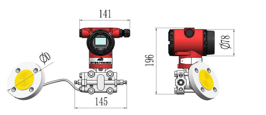
Dimens Ion Figure
Selection Table
- Measuring range: 0... 5000 kpa can be customized
- Display unit: LCD LCD screen
- Power supply voltage: 12... 36VDC
- Output signal: 4... 20mA,HART
- Measuring accuracy: 0.5,0.2% F.S.
- Repeatability: ≤0.1% full scale
- Measuring hysteresis: ≤ ±0.01% full scale
- Stability: < 0.01%/ year
- Medium temperature: -30... 300 ℃
- Ambient temperature: -30... 85 ℃
- Electrical connection: Fastener, M20*1.5, NPT1/2
- Protection grade: IP65
- Explosion-proof mark: flameproof type EXDIICT6,
- intrinsically safe EXIA IICT6
- Stainless steel and Hastelloy Cr process isolation diaphragm
- Single isolation diaphragm design
- stable performance, high precision, high temperature resistance
- A variety of optional filling liquid, can meet the requirements of different occasions
- Range, zero external continuous adjustable
- Adjustable damping and high pressure resistance
Mainly used for liquid and gas measurement such as: food, chemical, paper, medicine and other hygienic cleaning requirements of high temperature requirements, high viscosity medium and corrosion resistance needs occasions.
| code | range | code | range | code | rang | ||||||||||
| GP1 | -100...0kPa | GP7 | 0...500kPa | GL5 | 0...5m | ||||||||||
| GP2 | -100...100kPa | GP8 | 0...2500kPa | GL6 | 0...6m | ||||||||||
| GP3 | -100...500kPa | GP9 | 0...5000kPa | GL10 | 0...10m | ||||||||||
| GP4 | 0...35kPa | GL1 | 0...1m | GL15 | 0...15m | ||||||||||
| GP5 | 0...100kPa | GL2 | 0...2m | GL20 | 0...20m | ||||||||||
| GP6 | 0...250kPa | GL3 | 0...3m | GL25 | 0...25m | ||||||||||
| note :1bar=0.1MPa=100KPa=1.0197kg/cm² |
|||||||||||||||
| PN52 C- |
GP1 | 4 | D2 | M2 | L3 | A | A | specification | |||||||
| PN52C | PN52C series pressure (liquid level) | ||||||||||||||
| GP | Optional range (see range table) | ||||||||||||||
| GM0 | Range: 0-1.0 MPa | ||||||||||||||
| GM1 | Range: 0-1.6 MPa | ||||||||||||||
| GM2 | Range: 0-2.5 MPa | ||||||||||||||
| GM4 | Range: 0-4.0 MPa | ||||||||||||||
| GM1 | Range: 0 to 10 mpa | ||||||||||||||
| GL | Liquid level range (see range table) | ||||||||||||||
| 4 | Output 4... 20mA | ||||||||||||||
| H | Output 4... 20mA+HART | ||||||||||||||
| D2 | DN25 flange installation | ||||||||||||||
| D5 | DN50 flange installation | ||||||||||||||
| D8 | DN80 flange installation | ||||||||||||||
| K5 | Clamp type (50.5mm outside diameter) | ||||||||||||||
| G | Self- Clinching Fasteners | ||||||||||||||
| M2 | Electrical interface M20*1.5 inner teeth | ||||||||||||||
| N2 | Electrical interface NPT1/2 inner teeth | ||||||||||||||
| L3 | Capillary Length L (m) -- Standard 3 m | ||||||||||||||
| LA50 | Inserting barrel length 50 (mm) - optional | ||||||||||||||
| A | Liquid stainless steel diaphragm 316L | ||||||||||||||
| B | Liquid polytetrafluoroethylene PTFE coating | ||||||||||||||
| C | Hastelloy alloy C coating | ||||||||||||||
| D | Monel metal | ||||||||||||||
| A | standard form | ||||||||||||||
| B | flame-proof type | ||||||||||||||
| C | intrinsic safety type | ||||||||||||||
| Optional accessories | A1 | A1: LCD display header A2: No display | |||||||||||||
| B1 | B1 tube mounting bending support: B2 plate | ||||||||||||||
| B3 | B3: Flat support for pipe mounting | ||||||||||||||
| C1 | 1/4NPT | ||||||||||||||
| C2 | T-thread joint M20x1.5 | ||||||||||||||
| C3 | Weld 14 pressure tubes at the back of 1/2NPT pressure transition joint |
||||||||||||||
| * The type selection table is only for technical selection, and the corresponding type of the factory model is reflected by the code. |
|||||||||||||||
Shanghai Kayuan Electronic
Technology Co., Ltd.
Technology Co., Ltd.
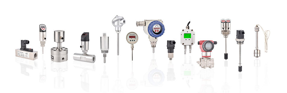
Shanghai Kayuan Electronic Technology Co.,Ltd is an enterprise specializing in the production and R & D of industrial sensors and controllers. Its main products include switches and sensors for flow, pressure, temperature, and liquid level. Capacitive pressure (liquid level) transmitter-PN52C Suppliers in China.
In 2008, our assembly plant was established in Shanghai China,PAKU INTELLIGENT EQUIPMENT(SHANGHAI)CO.,LTD a subsidiary of Kayuan to produce the PAKU series of products. As Capacitive pressure (liquid level) transmitter-PN52C Factory, PAKU products are now widely used in different industries, including automation complete sets of equipment, petroleum equipment, chemical equipment, power equipment, welding equipment, steel equipment, metallurgical equipment, automobiles, and water treatment. We adopt advanced technology and manufacturing processes across the board. With our professional design and production technology, comprehensive product lines, excellent quality, and sales network services, we can not only provide users with timely and professional technical support but also offer high - quality one - stop services.
We have served many customers at home and abroad, and offer Capacitive pressure (liquid level) transmitter-PN52C Wholesale, our products are sold to countries such as Canada, the United States, Brazil, Indonesia, Vietnam, Thailand, and Russia. We welcome extensive cooperation with OEM and ODM customers.
information
 [email protected]
![]() +86-13386111894 / +86-021-37566990
+86-13386111894 / +86-021-37566990
![]() B-4th Floor, Lane 1313, Nanting Road, Nanqiao Town, Fengxian District, Shanghai, China
B-4th Floor, Lane 1313, Nanting Road, Nanqiao Town, Fengxian District, Shanghai, China

Product Links