 en
en English
 Русский
 España
 عرب .
عرب .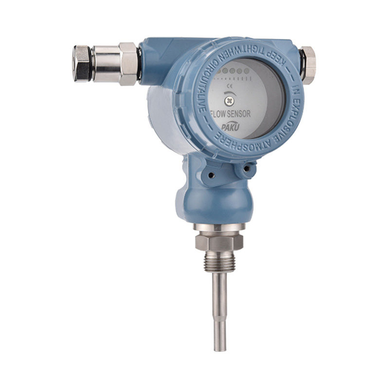

If you need any help, please feel free to contact us
inquire
If you have any further questions, please call +86-021-37566990 or fill out the inquiry form.
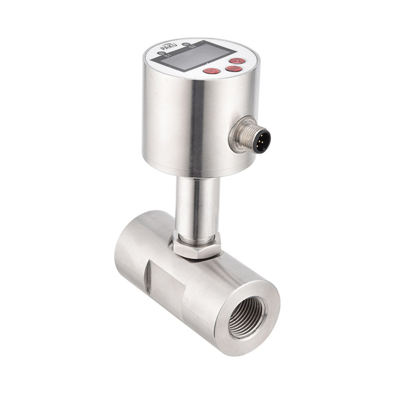
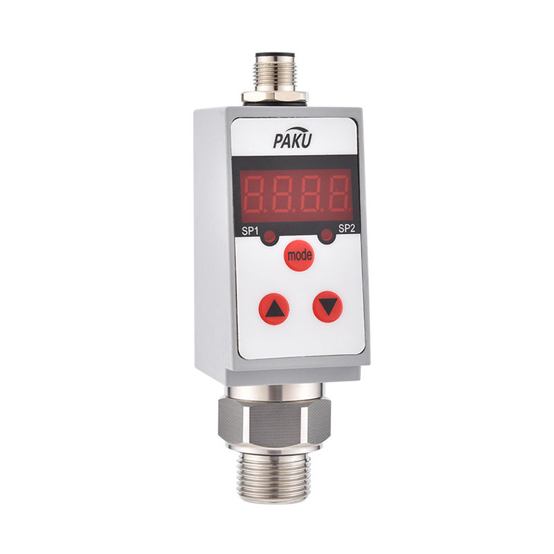
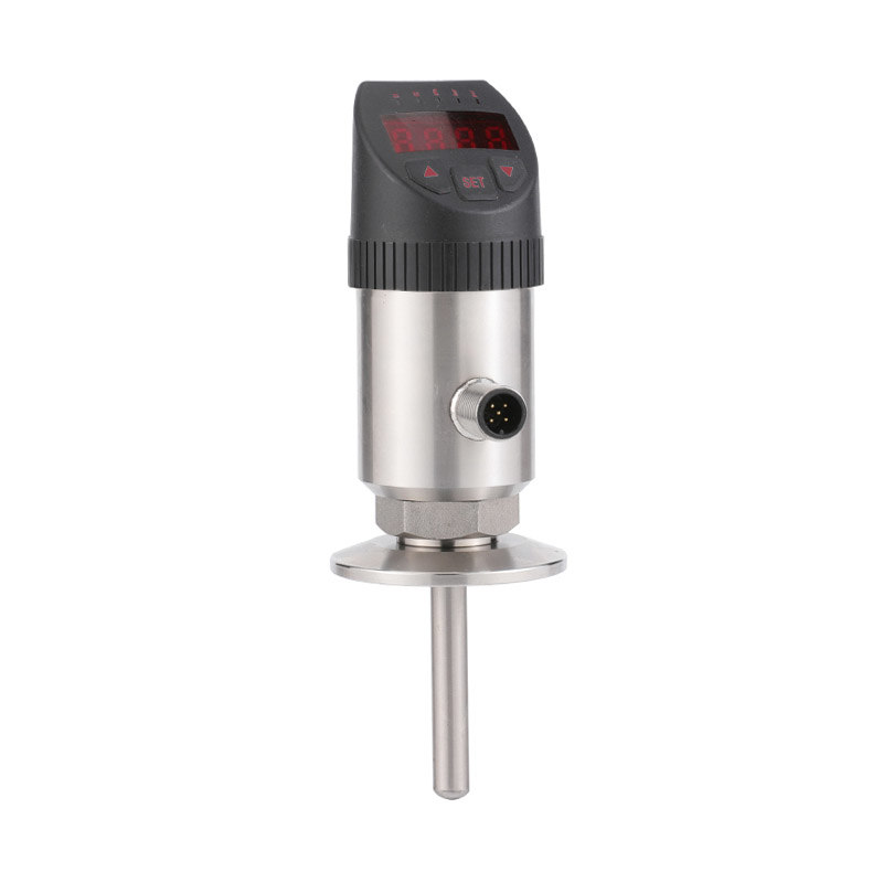
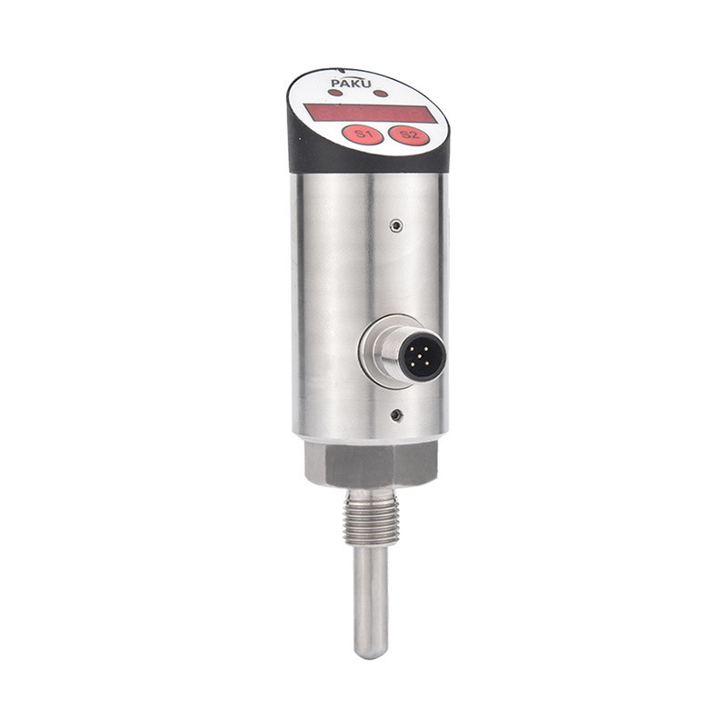
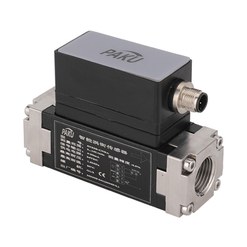
Get coupons PDF DownloadIntelligent vortex sensor-SN53B
Product introduction
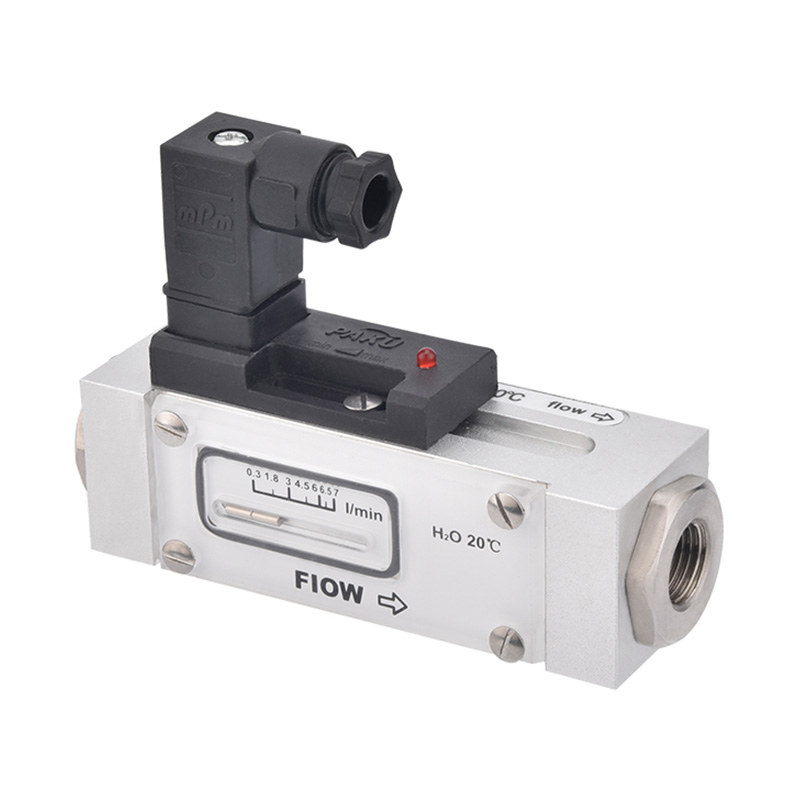
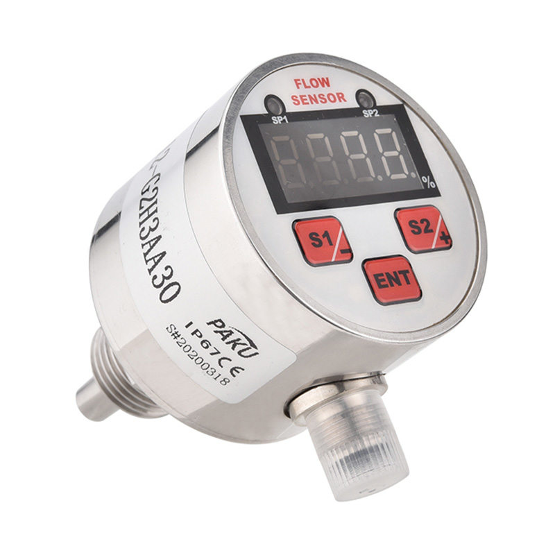
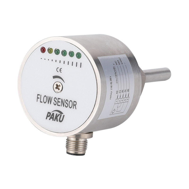
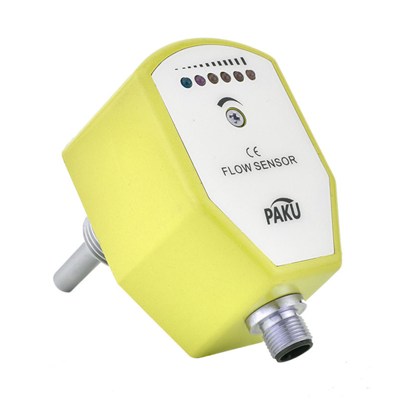
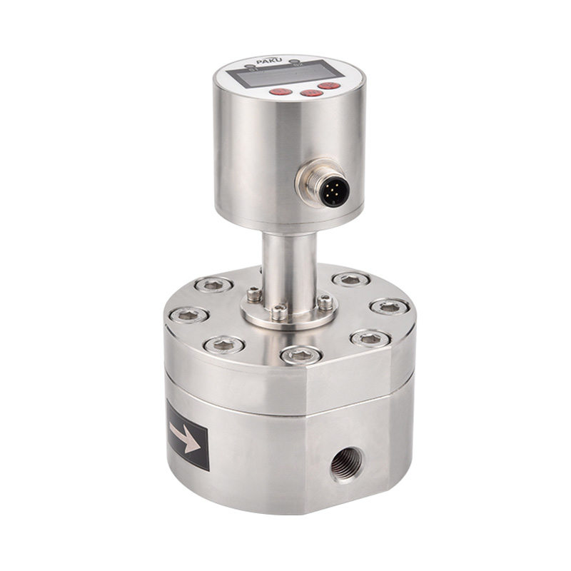
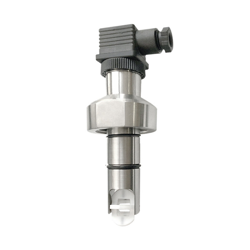
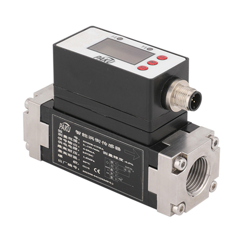
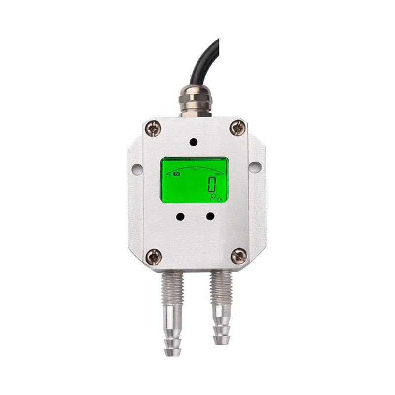
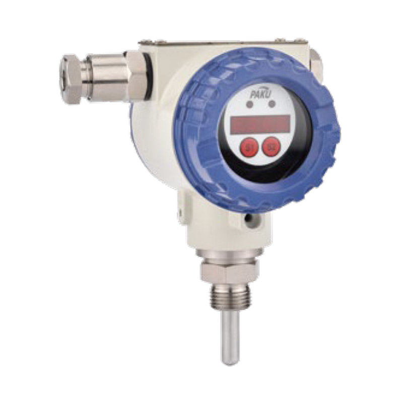
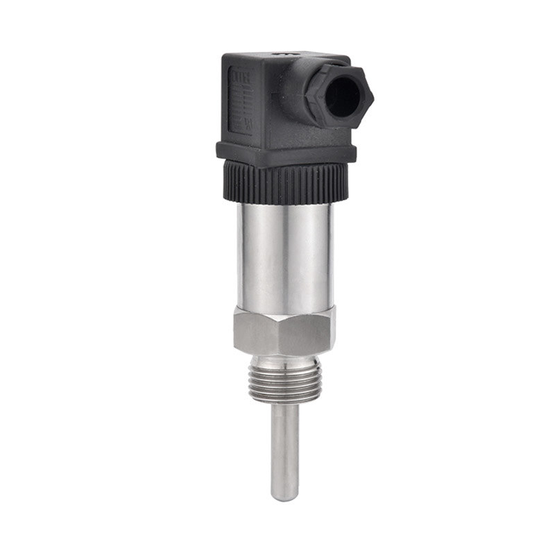
SN53B series intelligent vortex flow temperature sensor based on Carmen vortex principle, Carmen vortex is a Hungarian-American scientists von Carmen in 1911 observed and studied the phenomenon: when the fluid around a non-fluid linear object, the object tail flow on both sides of the left and right side of the production of pairs of alternately arranged, rotating in the opposite direction of the opposition to the so-called vortex. This vortex generation has a cycle, alternating changes in the nature of the frequency of change is proportional to the speed of the fluid, which is the Kamen vortex phenomenon, the specific relationship for the relationship Sr = fd / V. Vortex flowmeter is the use of this phenomenon is the nature of the vortex flow meter through the measurement of the frequency of vortex shedding to determine the speed of the fluid or the flow rate of the support of the support of the flowmeter. Has the advantages of small size, easy to set up, etc., built-in intelligent circuit, can be set arbitrarily flow upper and lower limits of the alarm value, can be remotely monitored real-time flow conditions, the full range of parameters on-site arbitrary settings.
Another high-precision sensor for temperature measurement, the signal is processed by the rear processing circuit and converted into a standard industrial electrical signal output and display, can be arbitrarily set the upper and lower limits of the temperature alarm value, can be remotely monitored the real-time temperature conditions, the full parameters of the site arbitrary settings.
Technical Indicators
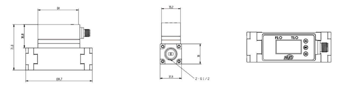
Dimension Drawing
Wiring Diagram (5-pole)
Wiring Diagram (8-core)
Selection Table
| Suitable media | Liquid (but with a viscosity of 3 mPa-s [3CP] or less) | ||||||
| Flow rate range | 0.5--4L/min | 2--16L/min | 5--40L/min | 10--100L/min | 20--200L/min | ||
| Medium temperature | 0-90°C (unfrozen or non-condensing) | ||||||
| Display unit | Instantaneous flow rate:L/min Accumulated flow rate:L/min | ||||||
| Accuracy | Display value:±5%Analogue output:±3 | ||||||
| Repeatability | ±1% | ||||||
| Pressure resistance | 15bar | ||||||
| Pressure loss | Below 45KPa at maximum flow rate | ||||||
| Switching output | Output | 2-way PNP or NPN output | |||||
| Maximum load current | 80mA | ||||||
| Supply Voltage | DC12-24V ±10% | ||||||
| Response Time | 0.5s/1s/2s | ||||||
| Output Protection | Short circuit protection | ||||||
| Output Modes | Flow rate | Hysteresis mode, upper and lower limit comparison mode, totalised output mode, totalised pulse output mode selectable | |||||
| Temperature | Hysteresis mode, upper and lower limit comparison mode selectable | ||||||
| Analogue outputs | Voltage Output | Output voltage:1~5V Output impedance:1kΩ | |||||
| Current Output | Output current:4~20mA Maximum load impedance:300Ω at DC12V, 600Q at DC24V | ||||||
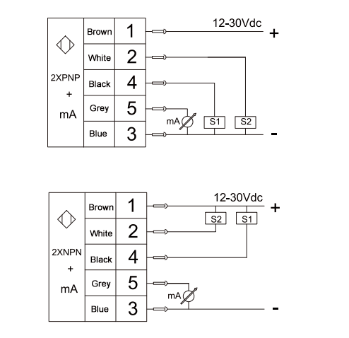
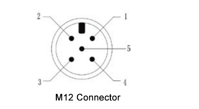
| Needle | Cable | Signal |
| 1 | Brown | Power supply |
| 2 | White | Switch 2 |
| 3 | Blue | GND |
| 4 | Black | Switch 1 |
| 5 | Grey | mA/pulse P |
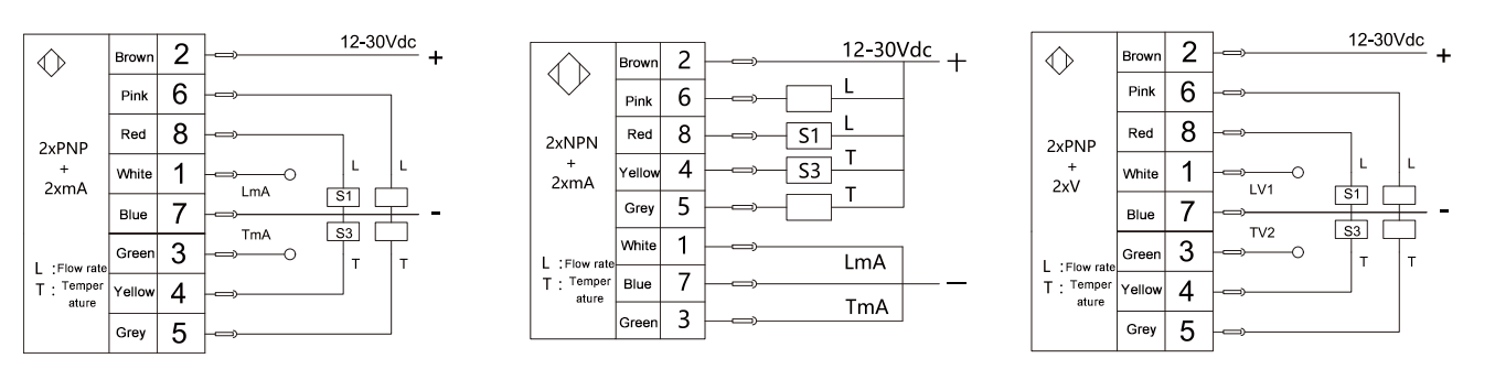
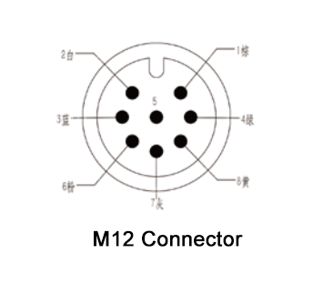
| Needle | Cable | Signal |
| 1 | White | Flow mA |
| 2 | Brown | Power supply + |
| 3 | Green | Temperature mA |
| 4 | Yellow | T1 temperature switching quantity |
| 5 | Grey | |
| 6 | Pink | |
| 7 | Blue | Power supply - |
| 8 | Red | L1 switching quantity |
| SN53B- | A | P | A | B | T | Detailed description | ||||||||||||
| SN53B- | SN53B Series Intelligent Vortex Sensor | |||||||||||||||||
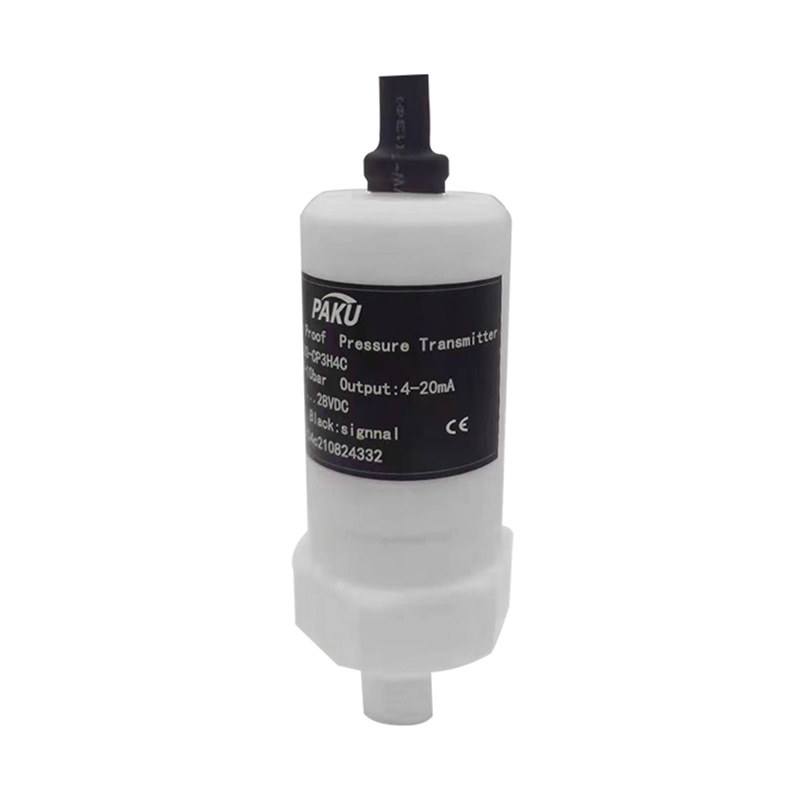
| B | Model B: Plastic body, stainless steel two-end interface with display | |||||||||||||||||
| B1 | Model B1: Plastic body with stainless steel interface without display (no switching function) | |||||||||||||||||
| P | PNP output (for models with display only) | |||||||||||||||||
| N | NPN output (for models with display only) | |||||||||||||||||
| A | Flow rate range: 0.5-4L/min Thread: G3/8 female thread | |||||||||||||||||
| A1 | Flow rate range: 0.5-4L/min Thread: RC3/8 female thread | |||||||||||||||||
| B | Flow rate range: 2-16L/min Thread: G1/2 female thread | |||||||||||||||||
| B1 | Flow rate range: 2-16L/min Thread: RC1/2 female thread | |||||||||||||||||
| C | Flow rate range: 5-40L/min Thread: G1/2 female thread | |||||||||||||||||
| C1 | Flow rate range: 5-40L/min Thread: RC1/2 female thread | |||||||||||||||||
| D | Flow rate range: 10-100L/min Thread: G1 female thread | |||||||||||||||||
| D1 | Flow rate range: 10-100L/min Thread: RC1 female thread | |||||||||||||||||
| F | Flow rate range: 10-100L/min Thread: G3/4 female thread | |||||||||||||||||
| F1 | Flow rate range: 10-100L/min Thread: RC3/4 female thread | |||||||||||||||||
| Optional without display | A | 1 analogue 4-20MA output (flow rate) | ||||||||||||||||
| B | 1 analogue 1-5V output (flow rate) | |||||||||||||||||
| C | RS485 communication (flow rate) | |||||||||||||||||
| S | One way 4-20mA + one way RS485 output for flow and temperature | |||||||||||||||||
| Unselectable without display | D | 2 analogue 4-20MA outputs (temperature, flow) | ||||||||||||||||
| E | 2 analogue 1-5V outputs (temperature, flow) | |||||||||||||||||
| E1 | Switching: two switching channels for flow rate Analogue : One 4-20MA output for flow rate |
|||||||||||||||||
| E2 | Switching quantity: flow rate two switching quantity Analogue : 1-5V output for flow rate |
|||||||||||||||||
| F1 | Switching quantity: one switch for temperature and one switch for flow rate Analogue: 4-20MA output for flow rate one way |
|||||||||||||||||
| F2 | Switching quantity: temperature and flow rate each one switching quantity Analogue: 1-5V output for flow rate all the way |
|||||||||||||||||
| F3 | Switching quantity :Temperature, flow rate all the way switching quantity Analogue : Temperature 4-20MA output all the way |
|||||||||||||||||
| F4 | Switching quantity: temperature, flow rate each way switching quantity Analogue : 1-5V output for temperature all the way |
|||||||||||||||||
| G1 | Switching quantity: temperature, flow rate each one way switching quantity Analogue : 4-20MA output for each of temperature and flow rate |
|||||||||||||||||
| G2 | Switching quantity: temperature, flow rate each one way switching quantity Analogue : 1-5V output for each of temperature and flow rate |
|||||||||||||||||
| R1 | Switching quantity: two switching quantities for flow rate RS485 communication |
|||||||||||||||||
| R2 | Switching quantity: two switching quantities for temperature RS485 communication |
|||||||||||||||||
| R3 | Switch quantity: one switch quantity for each temperature and flow rate RS485 communication |
|||||||||||||||||
| No temperature no need to choose | T | Default temperature range: 0-100°C | ||||||||||||||||
| T … | Customised temperature range | |||||||||||||||||
Shanghai Kayuan Electronic
Technology Co., Ltd.
Technology Co., Ltd.
Shanghai Kayuan Electronic Technology Co.,Ltd is an enterprise specializing in the production and R & D of industrial sensors and controllers. Its main products include switches and sensors for flow, pressure, temperature, and liquid level. Intelligent vortex sensor-SN53B Suppliers in China.
In 2008, our assembly plant was established in Shanghai China,PAKU INTELLIGENT EQUIPMENT(SHANGHAI)CO.,LTD a subsidiary of Kayuan to produce the PAKU series of products. As Intelligent vortex sensor-SN53B Factory, PAKU products are now widely used in different industries, including automation complete sets of equipment, petroleum equipment, chemical equipment, power equipment, welding equipment, steel equipment, metallurgical equipment, automobiles, and water treatment. We adopt advanced technology and manufacturing processes across the board. With our professional design and production technology, comprehensive product lines, excellent quality, and sales network services, we can not only provide users with timely and professional technical support but also offer high - quality one - stop services.
We have served many customers at home and abroad, and offer Intelligent vortex sensor-SN53B Wholesale, our products are sold to countries such as Canada, the United States, Brazil, Indonesia, Vietnam, Thailand, and Russia. We welcome extensive cooperation with OEM and ODM customers.

information
 [email protected]
![]() +86-13386111894 / +86-021-37566990
+86-13386111894 / +86-021-37566990
![]() B-4th Floor, Lane 1313, Nanting Road, Nanqiao Town, Fengxian District, Shanghai, China
B-4th Floor, Lane 1313, Nanting Road, Nanqiao Town, Fengxian District, Shanghai, China

Product Links