 en
en English
 Русский
 España
 عرب .
عرب .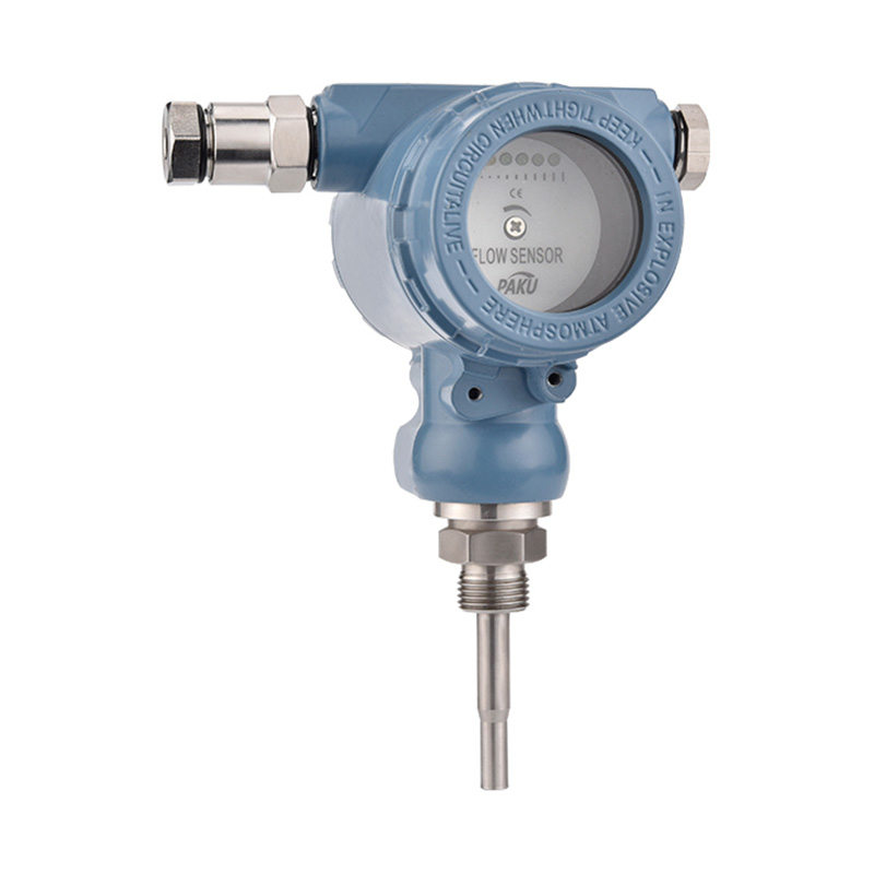

If you need any help, please feel free to contact us
inquire
If you have any further questions, please call +86-021-37566990 or fill out the inquiry form.
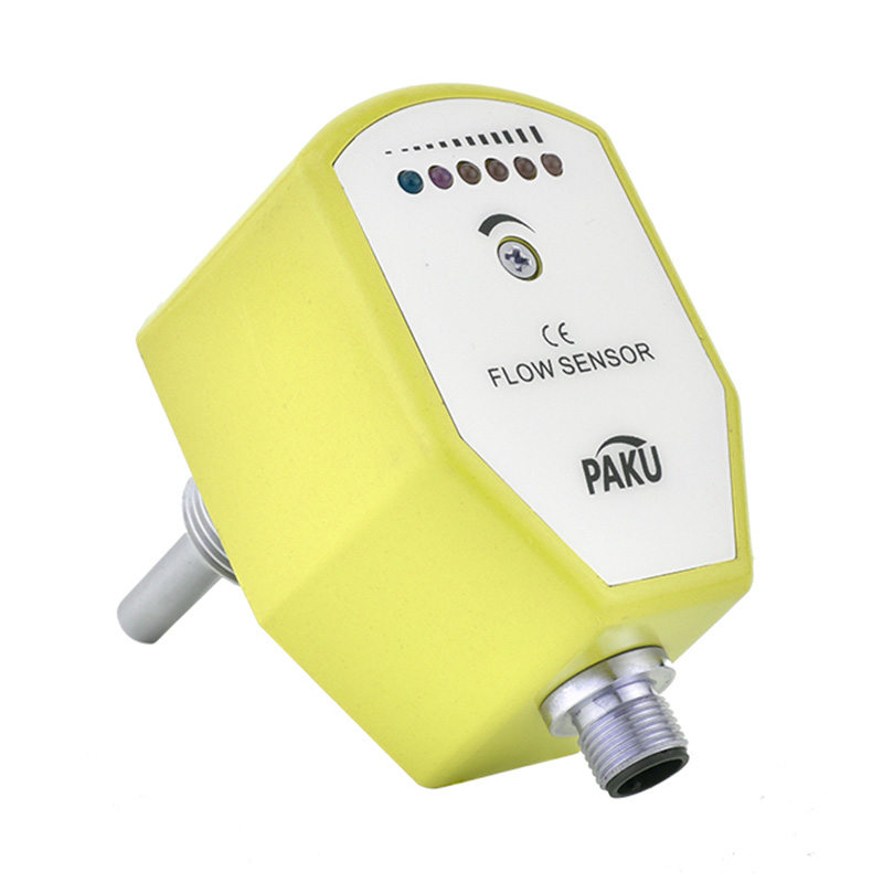
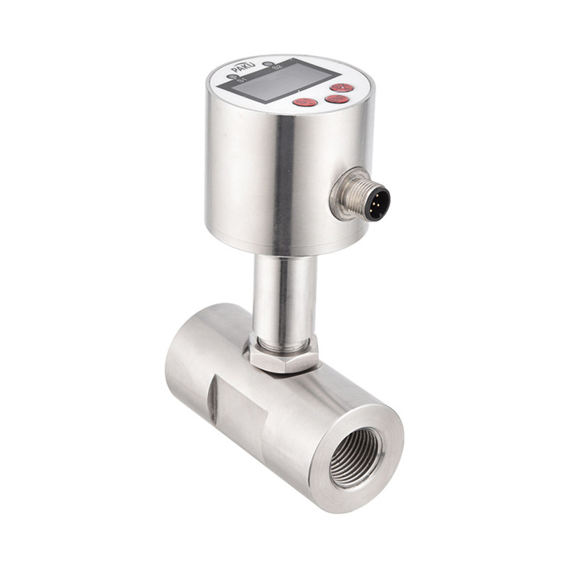
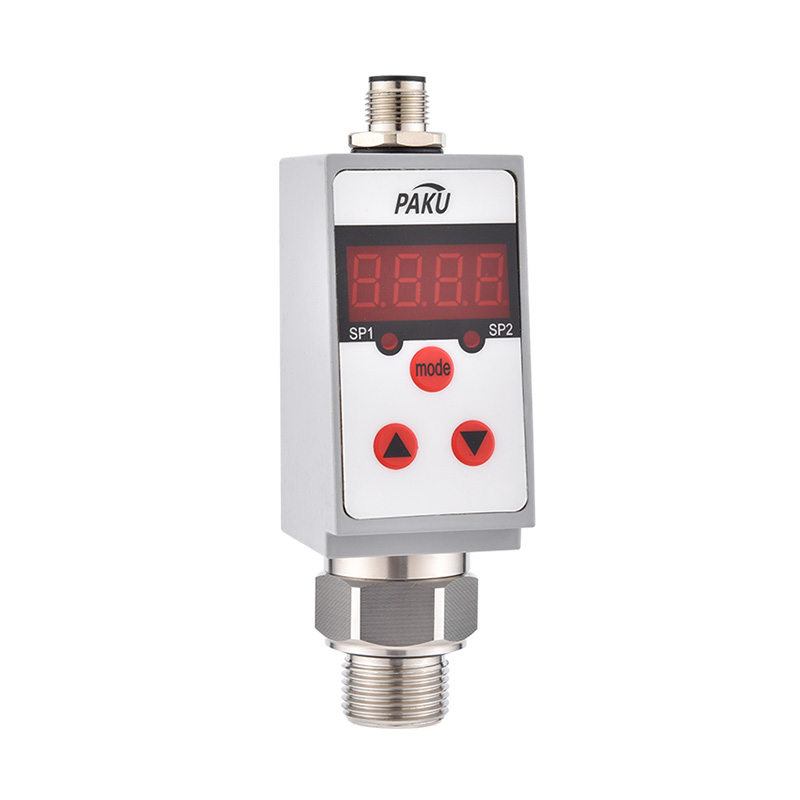
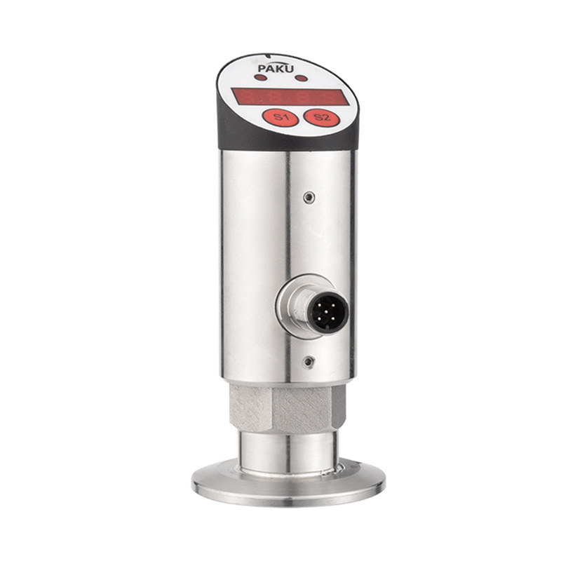
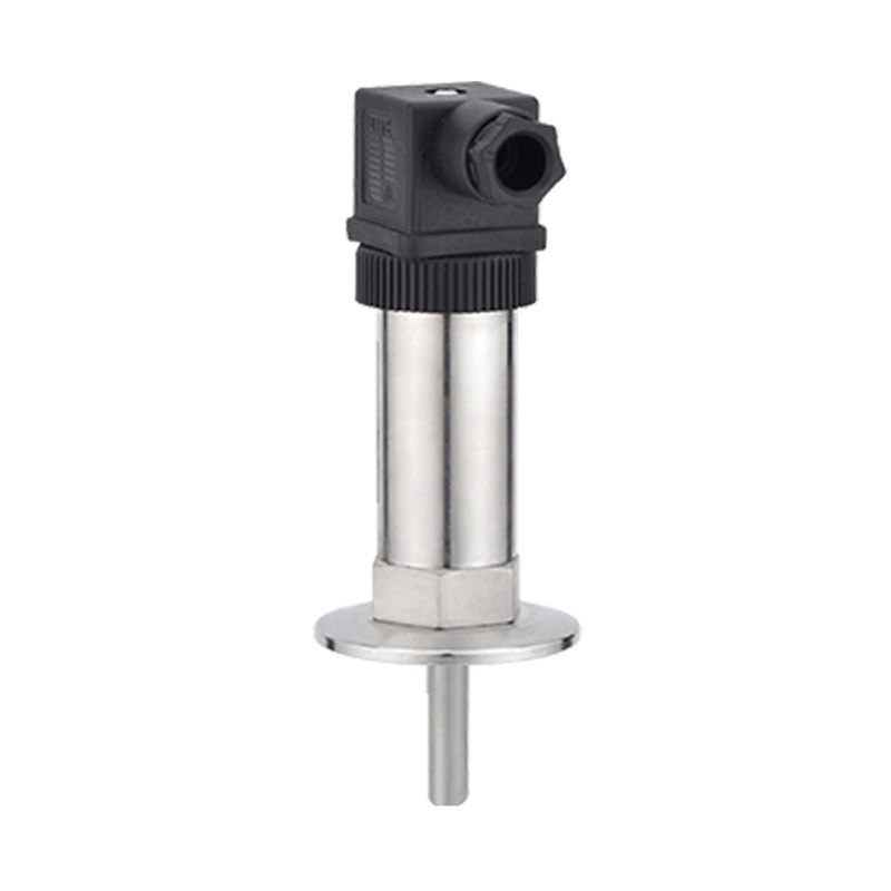
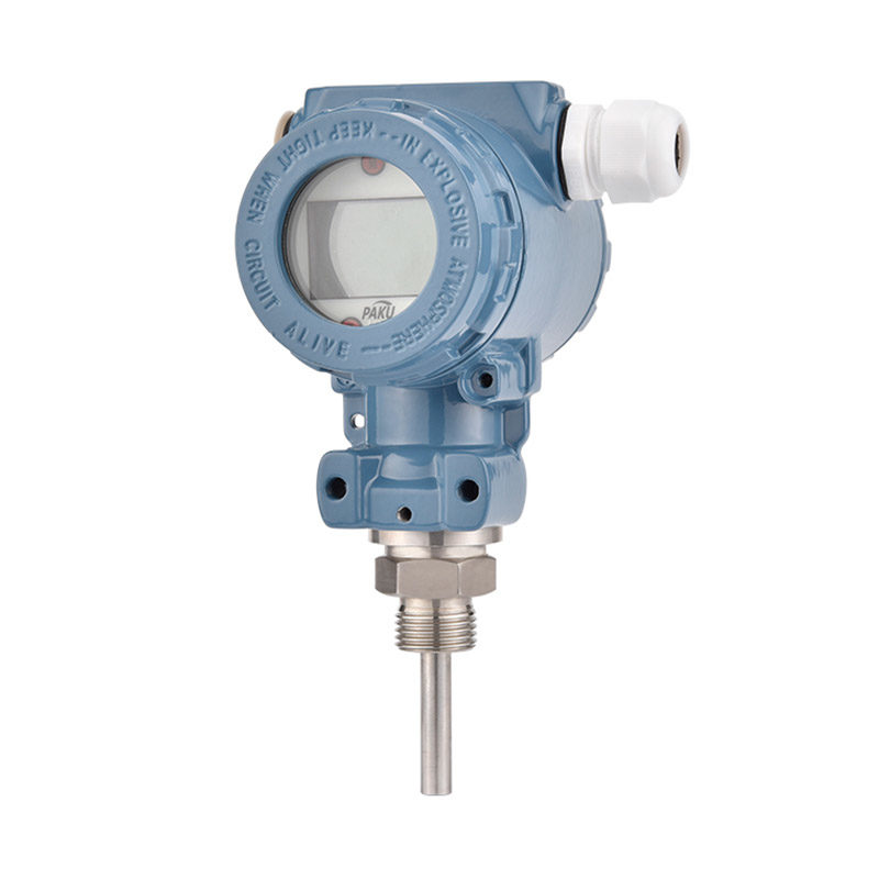
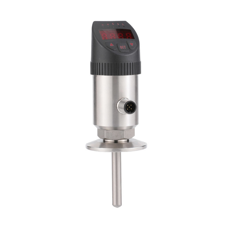
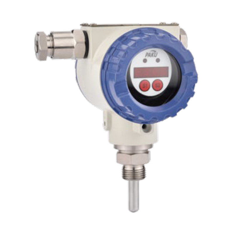
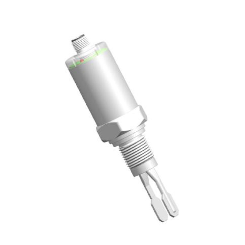
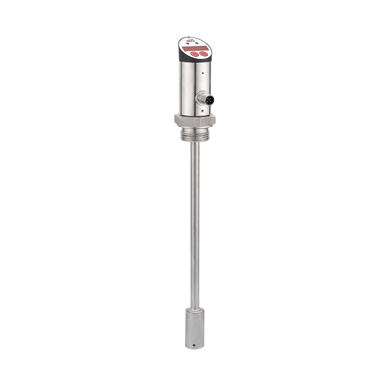
Get coupons PDF DownloadDigital electronic flow switch-SN12
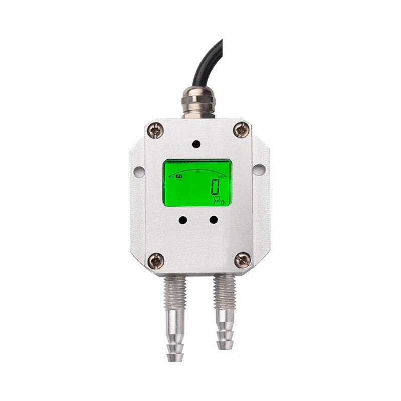
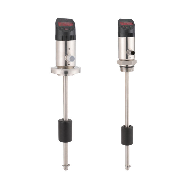
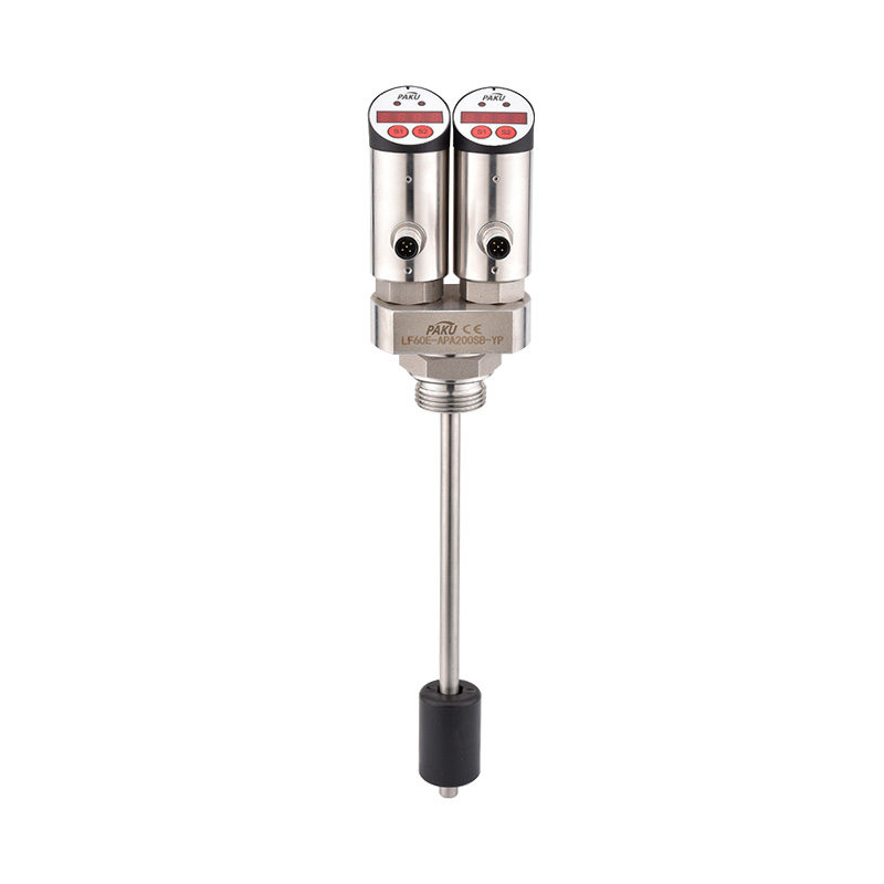
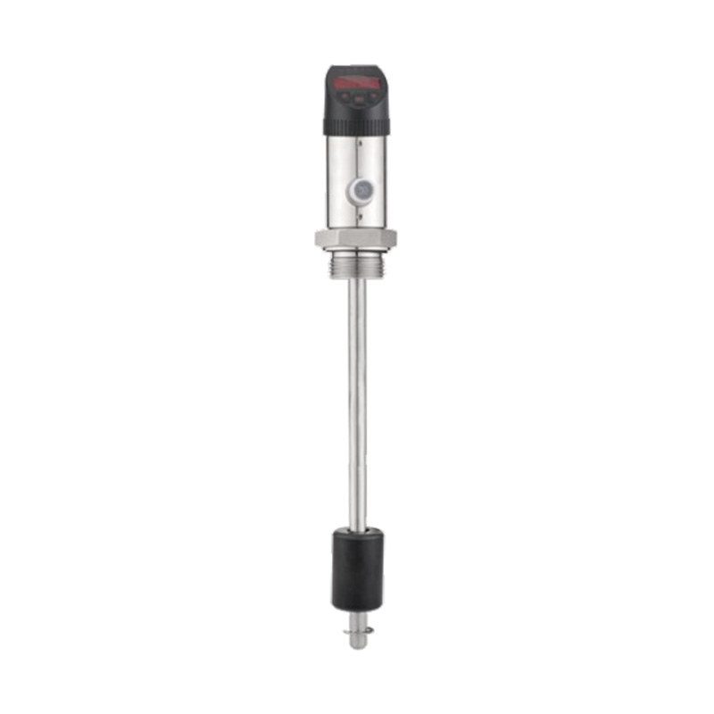
Product introduction
The principle of heat transfer temperature difference is not complicated, it is the use of heat propagation diffusion properties, the transfer of heat from the high temperature region to the low temperature region. Applied in the flow detection, the value of the temperature difference in the performance area corresponds to the size of the flow. The working principle of the heat transfer temperature difference, in the closed probe placed inside the heat module and temperature sensing module, the probe's heat transfer temperature difference is closely related to the measured medium flow rate, when the medium in the pipeline to a stable flow rate of flow, the sensing module receives the heat module sensing is a fixed value. When the flow rate of flow through the probe changes, the heat-sensing module will transmit the temperature difference signal with the change, after the processor will correspond to the flow rate of the results output.
1. Without any moving parts, so compared with mechanical flow switches it will not fail due to corrosion, breakage, baffle deformation and other reasons;
2. Suitable for flow monitoring of different media, including some impure liquid and gas media;
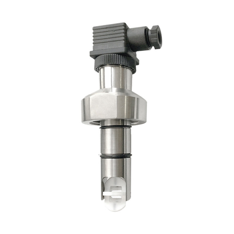
3. Plug-in installation mode, to meet a variety of pipe diameter installation requirements.
4. Wide range of flow detection, high precision, to meet customer requirements for the control of different flow rates of fluids.
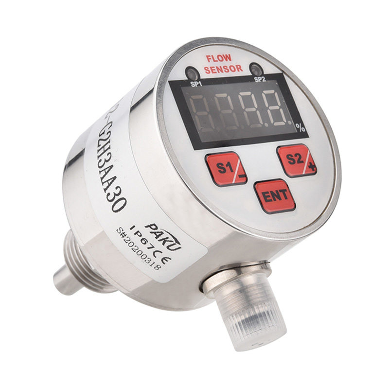
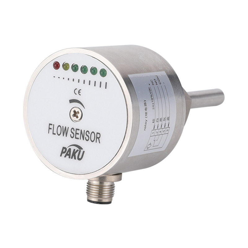
5. Digital display of the state of the media flow;
6. Key setting parameters, easy to operate.
7. Extra-long service life and maintenance-free design combined, so that your equipment to show a huge competitive advantage.
Product Application
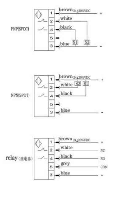
Wiring Diagram
Technical Specification
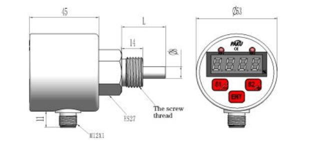
Dimension Figure
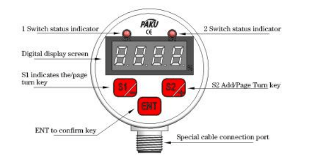
The Panel Figure
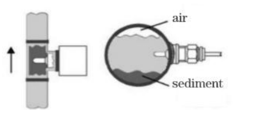
Installation Instructions
Selection Table
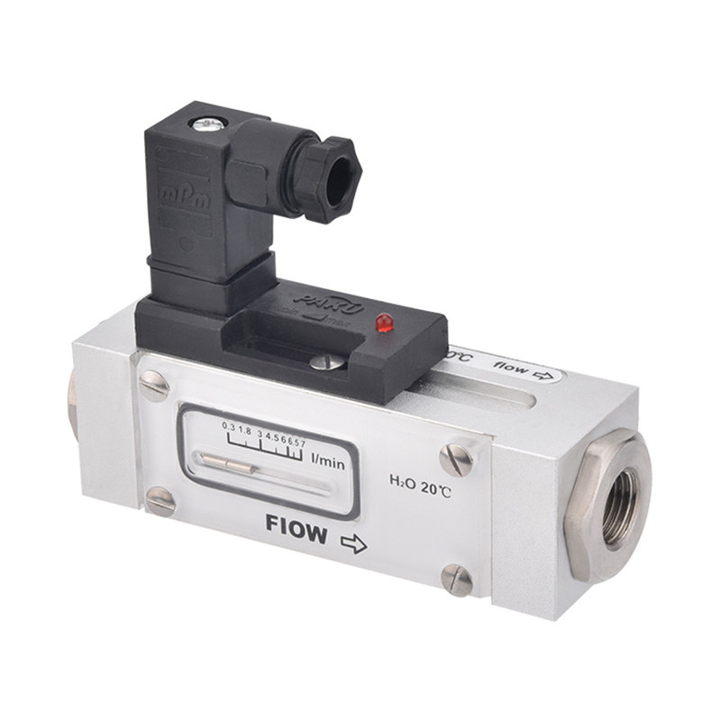
Pneumatic and hydraulic dual purpose, low flow rate alarm, can be used for pneumatic and hydraulic systems, can be used for circulating water, cutting fluid and lubricating oil cut-off detection, and pump idling protection.
Settings range: user-defined Settings
Signal output: PNP,NPN, relay, analog 4-20mA
Power supply: 24V±20%DC
Switch on current: maximum 400mA(PNP or NPN type)
Maximum 1A@48V (relay type)
No-load current: Max. 80mA
Flow indicator: LED digital tube
Setting method: press the key
Voltage range: 100bar
Temperature gradient: ≤4°C/S
Response time: 1-13s, typical 2s
initialization time: about 8s
Electrical protection: reverse phase, short circuit, overload protection
Protection grade: IP67
Medium temperature: -20-80°C
Ambient temperature: -20-80°C
Storage temperature: -20-100°C
Wiring mode :M12 connector/Optional 2 meters line optional
Material: Probe: stainless steel
stainless steel housing
Weight: about 0.4kg
For vertical installation, it should be installed on the pipe section flowing from bottom to top.
When mounted horizontally, the probe should be kept away from air and sediment.
| SN12 | - | G2H | A | 1 | 1 | X | A | 30 | specification | ||||
| SN12 | - | SN12 series electronic digital display flow | |||||||||||
| M1K | Interface thread M18*1.5 internal thread With the installation accessories, it is |
||||||||||||
| G2H | Interface thread G1/2 female thread | ||||||||||||
| G4H | Interface thread G1/4 male thread | ||||||||||||
| Custom threads, such as NPT1/2, type N12 | |||||||||||||
| A | DC DC24V±20% power supply | ||||||||||||
| 1 | PNP output | ||||||||||||
| 2 | NPNoutput | ||||||||||||
| 3 | relay output | ||||||||||||
| 1 | 1 switch output | ||||||||||||
| 2 | 1 switch output +1 4-20mA analog output | ||||||||||||
| X | Probe material: 304 stainless steel | ||||||||||||
| XL | Probe material: 316L stainless steel | ||||||||||||
| A | Connector type (standard with 2 meters of | ||||||||||||
| B | B Straight out | ||||||||||||
| 30 | Probe rod length unit mm (including thread) | ||||||||||||
| L | Customized probe rod length unit mm | ||||||||||||
| * The factory is standard equipped with electrical accessories M12 connector type ZL05-PU02FG * Select M18*1.5 internal thread installation mode, please pay attention to the selection of installation accessories * Customizable thread, H for external thread, K for internal thread * For selection of electrical accessories and installation accessories, please refer to the appendix page on page - * The selection table is only available for parameter selection, and the corresponding code is delivered. |
|||||||||||||
Shanghai Kayuan Electronic
Technology Co., Ltd.
Technology Co., Ltd.
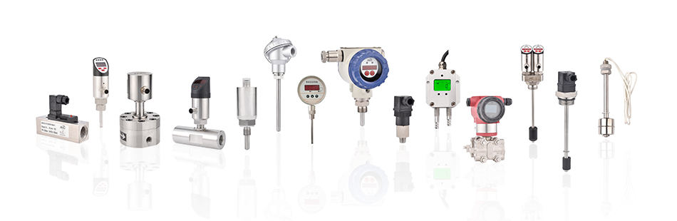
Shanghai Kayuan Electronic Technology Co.,Ltd is an enterprise specializing in the production and R & D of industrial sensors and controllers. Its main products include switches and sensors for flow, pressure, temperature, and liquid level. Digital electronic flow switch-SN12 Suppliers in China.
In 2008, our assembly plant was established in Shanghai China,PAKU INTELLIGENT EQUIPMENT(SHANGHAI)CO.,LTD a subsidiary of Kayuan to produce the PAKU series of products. As Digital electronic flow switch-SN12 Factory, PAKU products are now widely used in different industries, including automation complete sets of equipment, petroleum equipment, chemical equipment, power equipment, welding equipment, steel equipment, metallurgical equipment, automobiles, and water treatment. We adopt advanced technology and manufacturing processes across the board. With our professional design and production technology, comprehensive product lines, excellent quality, and sales network services, we can not only provide users with timely and professional technical support but also offer high - quality one - stop services.
We have served many customers at home and abroad, and offer Digital electronic flow switch-SN12 Wholesale, our products are sold to countries such as Canada, the United States, Brazil, Indonesia, Vietnam, Thailand, and Russia. We welcome extensive cooperation with OEM and ODM customers.

information
 [email protected]
![]() +86-13386111894 / +86-021-37566990
+86-13386111894 / +86-021-37566990
![]() B-4th Floor, Lane 1313, Nanting Road, Nanqiao Town, Fengxian District, Shanghai, China
B-4th Floor, Lane 1313, Nanting Road, Nanqiao Town, Fengxian District, Shanghai, China

Product Links