

 +86-13386111894
 Products & Solutions
 en
 English
 Русский
 España
 عرب .
If you need any help, please feel free to contact us
inquire
How Does a Differential Pressure Transmitter Work? A Practical Guide for Engineers
A maintenance engineer notices that the flow reading on a cooling-water line no longer matches a temporary clamp-on ultrasonic meter. The first instinct is to question the differential pressure transmitter. The short answer is straightforward: a differential pressure transmitter compares the pressure at two points in a process, converts that difference into an electronic signal, and reports the result to a control system. Everything else—isolating diaphragms, fill fluid, capacitive cells, and microprocessors—exists to make that comparison accurate, repeatable, and stable under industrial conditions.
What a Differential Pressure Transmitter Actually Measures
A DP transmitter has two process connections: a high-side inlet and a low-side inlet. The value it reports is the difference between the pressures applied to those two sides:
ΔP = Phigh - Plow
It does not directly measure gauge pressure, absolute pressure, or flow. It measures a difference, and the process engineer assigns meaning to that difference by the way the taps are arranged. The same transmitter supports flow, level, density, and filter monitoring, depending on the primary element and the piping around it.
The transmitter scales the difference to a standard output signal, typically 4-20 mA with HART, or a digital fieldbus signal, so a PLC or DCS can read it without extra converters.
| Term | Meaning |
| High-side pressure | Pressure applied to the high-pressure port, normally the upstream or bottom tap |
| Low-side pressure | Pressure applied to the low-pressure port, normally the downstream or top tap |
| Span | Full-scale calibrated differential pressure range of the transmitter |
| Static pressure | Common line pressure present on both sides at the same time |
| Turndown | Ratio of the maximum to the minimum span a transmitter can be calibrated to |
Core Working Principle: From Pressure Difference to Electrical Signal
Every DP transmitter follows the same signal path. Understanding that path is the fastest way to see how a differential pressure transmitter works in practice. The steps below describe what happens between the process tap and the control room.
- Process pressure acts on two isolating diaphragms, one connected to the high side and one to the low side.
- Each diaphragm transfers force through a fill fluid, usually silicone oil, to the sensing element.
- Inside the sensing element, a measuring diaphragm deflects by an amount proportional to the applied differential pressure.
- In a capacitive cell, the deflection changes the capacitance between the measuring diaphragm and two fixed electrodes. In a piezoresistive cell, the deflection strains resistors connected in a Wheatstone bridge circuit.
- A signal-conditioning ASIC detects the capacitance or resistance change and converts it into a linear electrical value.
- A microprocessor applies temperature and static-pressure compensation, then converts the value to a 4-20 mA or digital output proportional to ΔP.
The isolating diaphragms and fill fluid serve a critical purpose: they keep the process medium away from the precision sensing element while transmitting pressure faithfully. That is why the same transmitter design can handle steam, corrosive chemicals, or hygienic food media with only a change in wetted materials.
Capacitive, Piezoresistive, and Single-Crystal Silicon Sensing Cells
The sensing element is where transmitter designs differ the most. Each technology has distinct strengths, and knowing them helps during specification.
| Feature | Capacitive cell | Diffused silicon | Single-crystal silicon |
| Measuring principle | Diaphragm movement changes capacitance | Strain changes resistance of diffused resistors | Strain changes resistance of a monolithic crystal |
| Typical accuracy | 0.075% of span | 0.1-0.2% of span | 0.04-0.075% of span |
| Long-term stability | Good | Moderate | Excellent |
| Temperature effect | Compensated in firmware | Compensated in firmware | Inherently low |
| Typical cost | Medium | Lower | Higher |
For most process loops, any of these technologies works reliably. The distinction matters when the application needs a very low span in the kilopascal or pascal range, high turndown, or minimal recalibration over years of service.
Flow Measurement: The Most Common DP Application
Flow measurement with an orifice plate, venturi, or nozzle is the most widespread use of a DP transmitter. The restriction forces the fluid to accelerate, and the pressure downstream of the restriction drops. The differential pressure that appears across the element follows Bernoulli's principle:
Q = K × √ΔP
The square-root relationship matters in practice. If the transmitter is calibrated for 0-100 kPa, it outputs 25% of its full-scale signal at 25 kPa. But the flow through the restriction is proportional to the square root of the differential pressure, so 25 kPa corresponds to 50% of full-scale flow, not 25%.
The square-root function can be calculated inside the transmitter, in the DCS, or at a flow computer, but it must be handled somewhere or the reported flow will be inaccurate across the entire operating range.
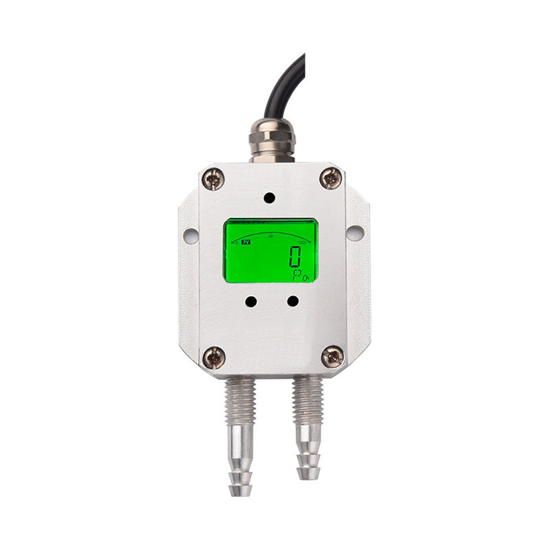
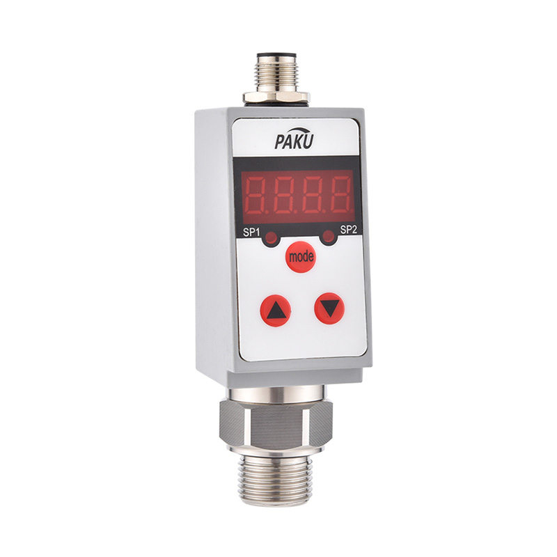
For line sizes above DN15, and where the permanent pressure loss of an orifice plate is acceptable, an orifice plate plus a DP transmitter remains one of the most repeatable and cost-effective flow measurements available. For standard installations, the general-purpose PN55 differential pressure transmitter from Paku Sensors covers typical spans and static-pressure ratings of industrial piping.General-Purpose Differential Pressure Transmitter for Flow and LevelThis DP transmitter suits standard industrial piping spans and static pressures, enabling orifice-plate flow measurement and hydrostatic tank level when connected with impulse lines.View Product →

Level, Density, and Filter Monitoring with the Same Transmitter
The same transmitter becomes a level instrument in a tank. In an open tank, the low side vents to atmosphere and the high side connects near the bottom. The measured DP equals the hydrostatic pressure of the liquid column:
ΔP = ρ × g × h
With a known density, level h is calculated directly from the differential pressure. In a closed pressurized tank, the low side connects to the vapor space above the liquid so that the vapor-space pressure is subtracted automatically.
If the level is held constant, the same equation measures density. That makes DP useful for interface detection, concentration monitoring, and slurry solids measurement. In filter and strainer monitoring, a clean element shows a small baseline ΔP; as the element loads with debris, ΔP climbs and triggers a backwash or replacement alarm at a preset threshold.
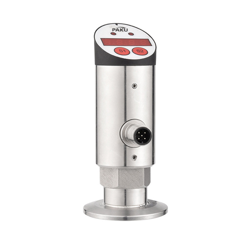
For low-range duties such as clean-room filter monitoring, HVAC duct pressure, and furnace draft, a micro-differential transmitter such as the PN53 from Paku Sensors gives the resolution needed to see changes of a few pascals.Micro-Differential Pressure Transmitter for Low-Range MonitoringDesigned for clean-room filter, HVAC duct, and furnace draft duties, its resolution detects changes of a few pascals, making it suitable for low-range pressure sensing.View Product →
How to Select a DP Transmitter for Your Process
Selection mistakes usually come from starting with accuracy rather than range and process conditions. Work through these six points before writing a specification:
- Define the normal and maximum differential pressure. Choose a span that puts the normal operating point at 40-80% of the calibrated range for the best repeatability.
- Check the static pressure rating. A transmitter with a 40 kPa span installed on a 4 MPa pipeline still needs a body rated for 4 MPa.
- Consider one-sided overrange. If one isolation valve closes while the other stays open, the cell may see full line pressure on one side. Overrange protection must be specified.
- Evaluate turndown. If the process DP varies from 2 kPa to 100 kPa, a 50:1 turndown prevents stocking multiple transmitters.
- Select wetted materials for the process fluid. Standard 316L stainless steel covers most media; corrosive fluids may require nickel-based alloys or PTFE isolation.
- Confirm hazardous-area certification. Explosive atmospheres require explosion-proof or intrinsically safe transmitters with the correct gas group and temperature class.
For a broader comparison of pressure sensing principles, our guide to pressure sensor types and selection covers the fundamentals in more detail.
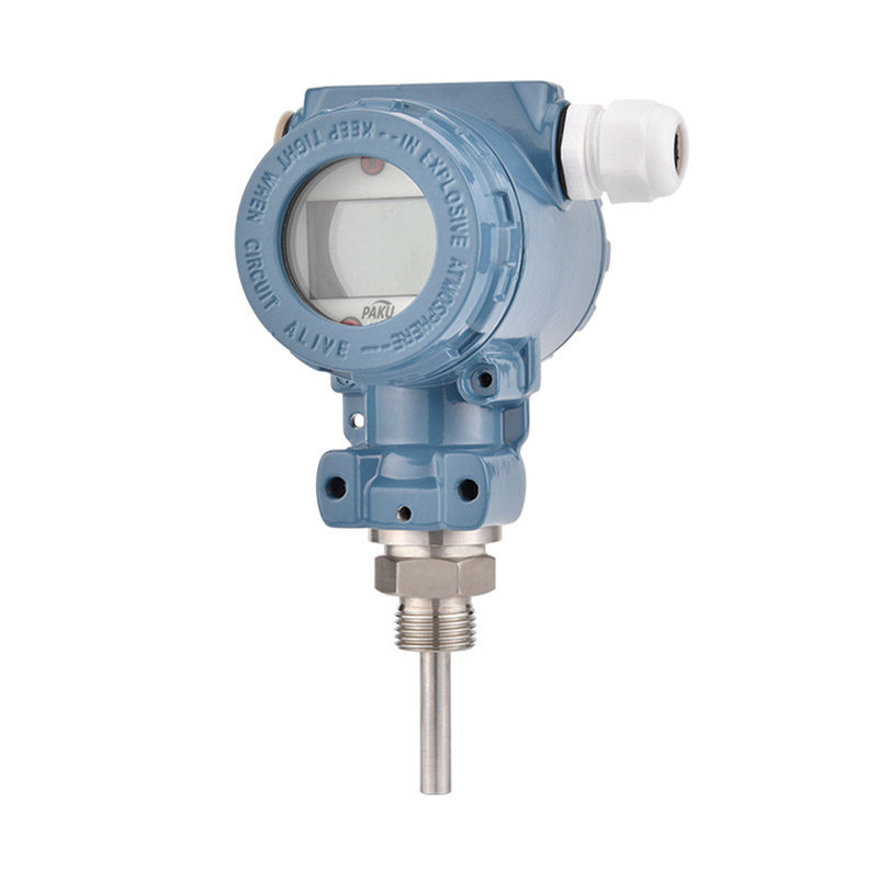
When an application demands the highest accuracy and long-term stability, for example in mass-balance calculations or loops with very low spans, single-crystal silicon sensing extends calibration intervals. The high-precision single-crystal silicon pressure transmitter PN30C from Paku Sensors is designed for that level of service.High-Precision Single-Crystal Silicon Pressure TransmitterBuilt for mass-balance and low-span applications, its single-crystal silicon sensor provides high accuracy and long-term stability, extending calibration intervals in demanding service.View Product →
Installation and Commissioning Basics
A well-selected transmitter still depends on the installation around it. Use a three-valve or five-valve manifold so that the transmitter can be isolated, equalized, and zeroed without shutting down the process. Route impulse lines with the correct slope: wet-gas lines slope downward toward the transmitter so condensate drains back, while liquid lines slope upward so trapped gas can escape. Fill liquid impulse lines with a fluid compatible with the process and bleed all air from the lines before commissioning.
After the transmitter reaches process temperature, perform a zero trim. A zero shift of a few hundred pascals is common when a cold instrument warms up to line temperature, and it creates a real error in low-range applications. Set damping time so the output is stable but fast enough to protect the process against genuine excursions.
A DP transmitter is, at its core, a difference-to-signal converter. A restriction creates a difference, a tank creates a difference, a clogged element creates a difference, and the transmitter reports it faithfully. Once that principle is clear, selection, calibration, and troubleshooting all become simpler.
If you are working through a DP transmitter specification, the Paku Sensors engineering team provides application support and custom configuration across the full pressure, flow, level, and temperature product families.
information
 [email protected]
 +86-13386111894 / +86-021-37566990
[email protected]
 B-4th Floor, Lane 1313, Nanting Road, Nanqiao Town, Fengxian District, Shanghai, China

Product Links