

 +86-13386111894
 Products & Solutions
 en
 English
 Русский
 España
 عرب .
If you need any help, please feel free to contact us
inquire
Flow Meter P&ID Symbols Explained: Reading Process Instruments and Tags
A P&ID can distinguish a magnetic flow meter from a turbine meter with nothing more than a circle, a short line, and a four-letter tag. That compact symbol carries the operating principle, the signal type, and the location of the instrument. Misreading it in a process diagram can create wrong assumptions about pressure loss, grounding, or downstream straight-run length.
This guide explains the flow meter P&ID symbol in practical terms. You will learn how to read the standard instrument bubble, decode the tag, and recognize the symbol variations used for orifice plates, venturis, rotameters, magnetic meters, turbine meters, and vortex meters. If you are evaluating hardware for an actual line, the same drawings help you define the technical requirements that match a real process industry application.
The Basic Flow Meter P&ID Symbol
The basic flow meter P&ID symbol is an instrument bubble: a circle attached to the process line with a thin connecting line. Inside the bubble, a tag code identifies what the device does. The primary sensing element, such as an orifice plate or a turbine wheel, is usually drawn separately as the flow element. A single flow loop may contain several symbols that work together.
The tag code is the fastest way to understand a flow measurement on a P&ID. It uses the ISA 5.1 lettering system, where the first letter defines the process variable and subsequent letters define the function.
| Tag Code | Meaning | Typical P&ID Role |
| FE | Flow Element | Primary sensing device such as an orifice plate, venturi, or rotameter |
| FT | Flow Transmitter | Converts the element signal and sends it to a controller or DCS |
| FIT | Flow Indicating Transmitter | Transmits the flow value and also displays it locally |
| FI | Flow Indicator | Local flow reading without a transmitted signal |
| FQ | Flow Totalizer | Integrates flow over time to track total volume or mass |
| FRC | Flow Recording Controller | Records the flow value and controls to a setpoint |
| FV | Flow Valve | Control valve that changes the flow rate in the line |
| FY | Flow Relay/Compute | Performs calculations such as square-root extraction or signal scaling |
Beyond the tag for the primary flow element, you will often see a nearby bubble for the transmitter. In modern P&IDs, the transmitter bubble may carry the same loop number with a suffix such as FT-1001. The line connecting the bubbles to the process may be drawn solid for field-mounted instruments or dashed for panel-mounted instruments. Many existing plants still follow ISA 5.1, while newer drawings may follow other standards such as ISO 14617. Regardless of standard, the flow meter P&ID symbol must clearly show what is installed in the field.
Element-Specific Flow Meter Symbols
Different flow meter technologies have separate P&ID symbol conventions because they sense flow in different ways. The element symbol matters for engineering review, installation planning, and maintenance.
Orifice Plate Flow Meter Symbol
The orifice plate appears as a small restriction in the pipe, often drawn as two narrow vertical marks or a short constricted line labeled FE. It uses differential pressure to infer flow. The transmitter taps the line upstream and downstream of the plate, and the flow computation uses square-root extraction. This symbol tells you the fluid will experience a permanent pressure loss.
Venturi Tube Flow Meter Symbol
The venturi meter symbol shows a converging section, a throat, and a diverging recovery section. It is also a differential pressure flow meter, but it recovers much more pressure than an orifice plate. Use this symbol when the P&ID shows a need for lower pressure loss in a larger line.
Rotameter Symbol
The rotameter, or variable area meter, is drawn as a vertical tapered tube with a float line. It gives a local visual flow indication and is common on purge lines, instrument air, and cooling water. In symbol form, it is usually tagged as either FE or FI, depending on whether the reading is transmitted.
Magnetic Flow Meter Symbol
A magnetic flow meter symbol represents an electromagnetic flow meter, often drawn with a flanged measuring tube and electrode marks near the process line. The key operating fact is that the fluid must be conductive. The symbol tells you it is an obstructionless measurement with no moving parts, but it also warns the designer to include enough straight pipe upstream and downstream. A pipe-mounted electromagnetic sensor is a common hardware match for this symbol.Electromagnetic Flow Meter for Conductive LiquidsThis obstructionless meter suits conductive fluids with no moving parts, matching the P&ID symbol highlighted. It is worth reviewing to support accurate flow measurement in process lines.View Product →
Turbine Flow Meter Symbol
The turbine meter symbol shows an in-line rotor or small fan wheel in the pipe, often tagged FE with a nearby FT or FIT. The rotor turns at a speed proportional to flow velocity, and a pickup coil generates a pulse output. The P&ID symbol will typically be accompanied by notes on minimum straight run and fluid cleanliness. A typical turbine flow sensor package contains the rotor, pickup coil, and preamplifier in one housing.Turbine Flow Sensor with Pulse OutputAn in-line rotor generates pulses proportional to flow velocity, ideal for clean fluids. The package includes rotor, pickup coil, and preamplifier, aiding reliable installation and straight-run planning.View Product →
Vortex Flow Meter Symbol
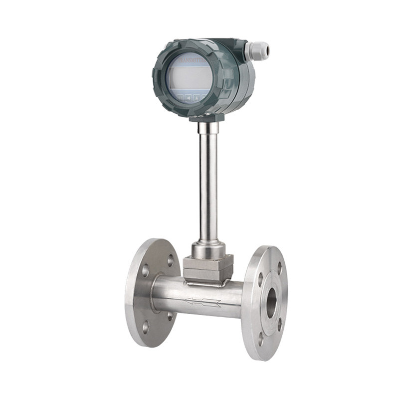
A vortex flow meter symbol indicates a bluff body in the pipe with a sensor behind it that detects alternating vortices. The frequency of vortices is proportional to flow velocity, so this meter works for liquid, gas, and steam across a wide temperature range. The symbol may include a shedder bar mark on the line. Intelligent versions add temperature compensation or a local display, which is why they appear in mass flow calculations.Intelligent Vortex Flow Meter for Steam and GasThis meter detects alternating vortices behind a bluff body, handling liquids, gas, and steam across a wide temperature range. Its compensation and display features simplify mass flow calculations.View Product →
How to Avoid Common Reading Mistakes
The flow meter P&ID symbol is easy to misread when you focus only on the circle and ignore the tag. Keep these rules in mind.
- Read the first letter first. A tag that starts with F is a flow function, not a pressure or temperature function.
- Do not assume a transmitter. If the tag is only FI, the device shows a local value and does not send a signal to a control system.
- Watch the element symbol. An orifice plate, venturi, rotameter, magnetic tube, turbine wheel, or vortex shedder all use different shapes and require different installation conditions.
- Check for straight-run notes. Magnetic and turbine meters need stable velocity profiles, and the notes next to the symbol define the required pipe lengths.
- Do not ignore the process line connection. Clamp-on sensors, insertion probes, and in-line meters have very different maintenance and pressure ratings.
Choosing the Right Flow Meter Symbol for Your Application
Symbol literacy helps during project review, but the final choice depends on process data: fluid conductivity, viscosity, temperature, pressure, acceptable pressure loss, and required accuracy. A P&ID symbol cannot show every detail. Use it as a starting point for the datasheet, then verify material compatibility and output signals with the instrument supplier.
If you are comparing products for the flow loops on your drawing, the engineering and manufacturing background behind Paku Sensors is described in the company overview. That context helps you confirm that the supplier understands both the symbol and the physical instrument behind it.
information
 [email protected]
 +86-13386111894 / +86-021-37566990
[email protected]
 B-4th Floor, Lane 1313, Nanting Road, Nanqiao Town, Fengxian District, Shanghai, China

Product Links