 en
en English
 Русский
 España
 عرب .
عرب .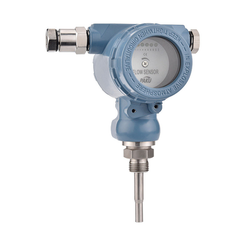

If you need any help, please feel free to contact us
inquire
If you have any further questions, please call +86-021-37566990 or fill out the inquiry form.
Get coupons PDF DownloadIntelligent Vortex Flow Sensor-SN53
Product introduction
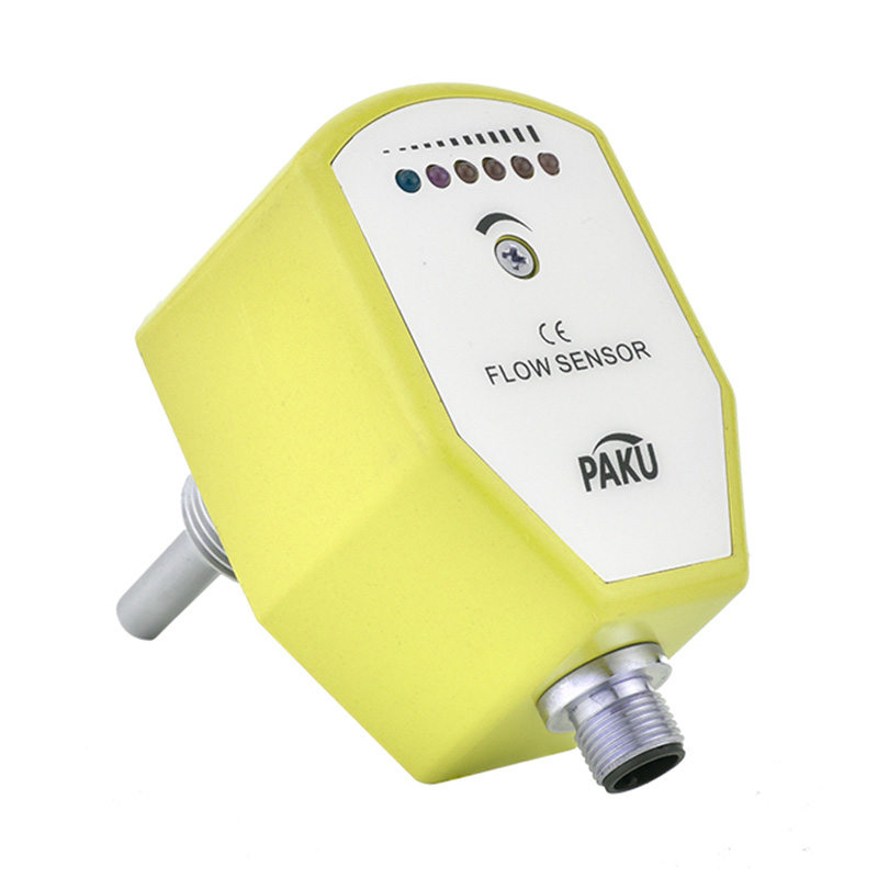
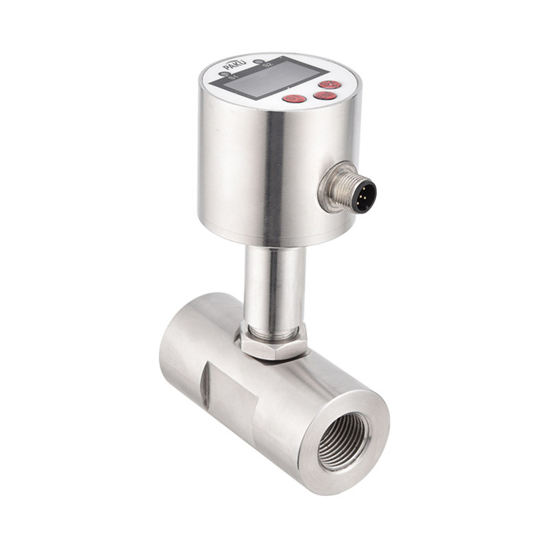
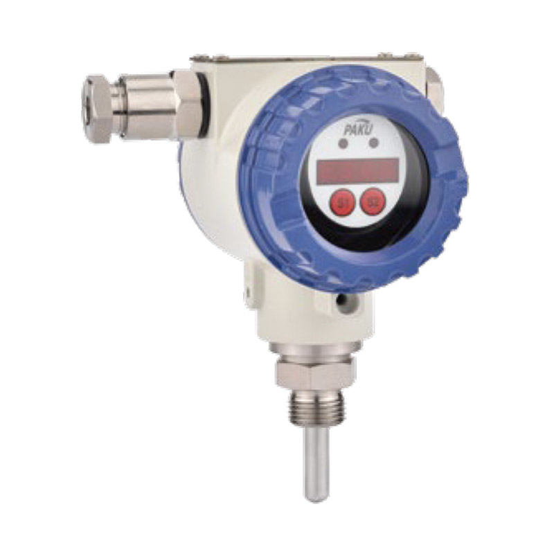
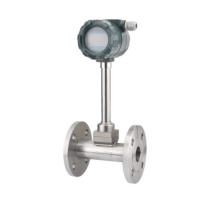
SN53 series vortex flowmeter is a kind of velocity type flow meter made according to Carmen vortex theory, using the principle of natural vibration of fluid and piezoelectric crystal or differential capacitor as the detecting part.
The product adopts unique differential technology, with isolation, shielding, filtering and other measures to overcome the similar products with poor seismic resistance, noise, small signal data disorder and other problems, and uses a unique detection probe encapsulation of new technologies and protective measures to ensure the reliability of the product.
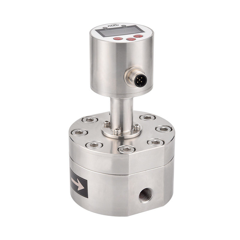
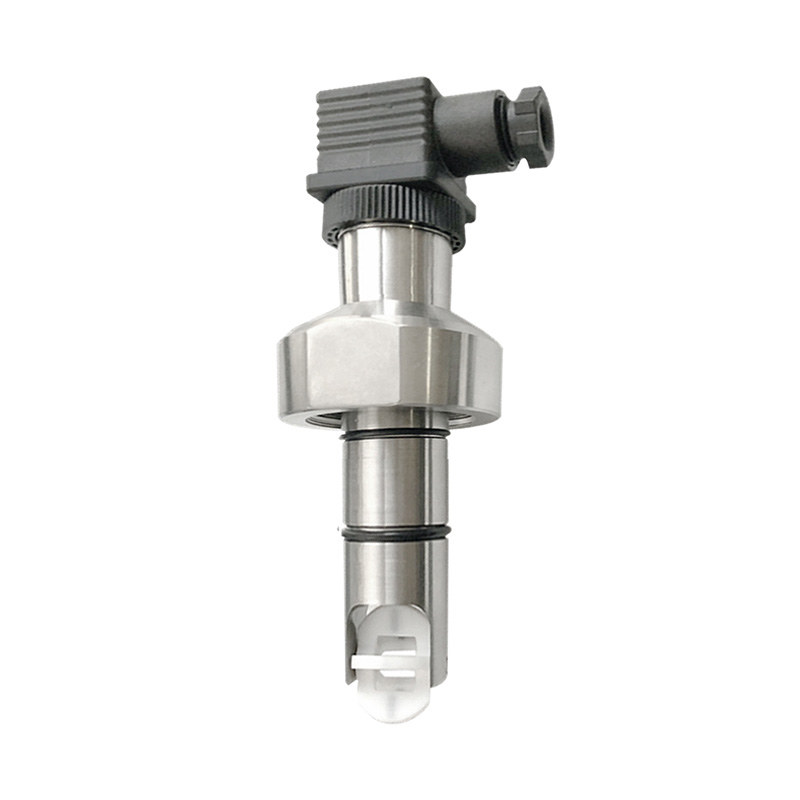
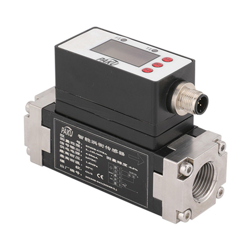
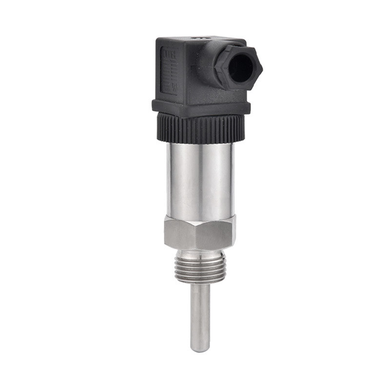
The product has basic type, temperature and pressure compensation of two types of measurement, the basic type of measurement of a single condition flow signal, temperature and pressure compensation of the integrated type can simultaneously measure the temperature, pressure, flow signal, after compensation, the output of the standard volume flow or mass flow. There are two types of structure: pipeline type and insertion type. It can be displayed on site or transmitted over a long distance, and can be networked with a computer to achieve centralised management. Each type has high temperature, high pressure, explosion-proof and other specifications, and there are split and whole structure to adapt to different measurement media and installation environment.
This product has a wide range than a series of advantages such as high precision, easy installation and maintenance and wide adaptability to the medium. It can be widely used in petroleum, chemical, metallurgy, machinery, food, paper, medicine, and urban pipeline heating, water supply, gas and other industries in a variety of low-viscosity liquids, gases, steam and other single-phase fluids, process measurement and energy-saving management.
Technical Description
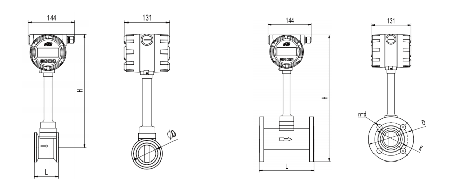
Dimension Drawing
Working Principle
Measurement Range
Dimensional Drawing 1 (Flange Connection Type)
Dimension Drawing 2 (Flange Clamping Type)
Selection Table
| Calibre | DN15 - DN300 | ||||||||||||||||||||||||||
| Measuring liquids | Saturated steam, superheated steam, liquid, gas | ||||||||||||||||||||||||||
| Accuracy | ±1.0, 1.5 (plug-in 2.5) | ||||||||||||||||||||||||||
| Measurement repeatability | 0.3 (R) | ||||||||||||||||||||||||||
| Nominal pressure | 1.6Mpa 、2.5MPa 、4.0MPa 及以上 | ||||||||||||||||||||||||||
| Fluid temperature | -40~250°C (normal type), 100~350°C (high temperature type) | ||||||||||||||||||||||||||
| Output Signal | 3-wire pulse output or 2-wire 4-20mA standard current | ||||||||||||||||||||||||||
| Power supply | +24VDC | ||||||||||||||||||||||||||
| Working environment | Temperature -25~60°C | ||||||||||||||||||||||||||
| Humidity | ≤90 RH | ||||||||||||||||||||||||||
Non-streamlinear vortex generator (resistive fluid) in the fluid, then from the vortex
The two sides of the vortex generator alternately produce two rows of regular vortices, which are called Karman vortex street as shown in Figure (I).
This type of vortex is called Karman vortex street as shown in Figure (I).
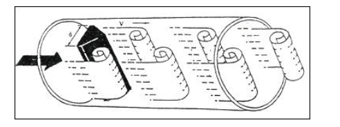
The vortex columns are arranged asymmetrically downstream of the vortex generator. Let the occurrence of vortex
Frequency of the vortex is f, the average velocity of the measured medium is V, the vortex generator meets the flow surface
Width of the vortex generator for d, the table body diameter for D, according to the principle of Carman vortex street, there is the following relationship:
f=StV/d
Equation (1)
Where: f a generator side of the Kamen vortex generated frequency
St a Strohal number (dimensionless number)
V - the average flow velocity of the fluid
d a vortex generator width
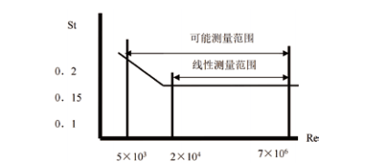
It can be seen that, by measuring the Kamen vortex separation frequency can be calculated instantaneous flow
The instantaneous flow rate can be calculated by measuring the Kamen vortex street separation frequency. The Strohal number (St) is a dimensionless unknown, and Fig. (ii) shows the Strohal number (St).
Strohal number (St) and Reynolds number (Re) relationship.
It can be seen that the instantaneous flow can be calculated by measuring the Kamen vortex separation frequency.
The instantaneous flow can be calculated by measuring the Kamen vortex separation frequency. The Strohal number (St) is a factorless unknown, and Figure (II) shows the Strohal number (St) versus the Reynolds number (Re).
Strohal number (St) and Reynolds number (Re) relationship.
K=N/Q(1/m³)
Formula (1)
Where:K=Instrument constant (1/m³).
N=number of pulses
Q=volume flow rate (m³)
| Instrument calibre (mm) |
Fluids | Gases | |||||||||||||||||||||||||
| Measurement range (m³/H) |
Output Frequency Range(Hz) |
small signal | Measurement range (m³/H) |
Output frequency range(Hz) | Small signal | ||||||||||||||||||||||
| 15 | 0.4 ~4 | 40 ~400 | 15 | 5.0-15 | 280 ~ 1200 | 100 | |||||||||||||||||||||
| 20 | 0.8 ~8 | 33 ~330 | 10 | 6 ~30 | 230 ~ 1100 | 80 | |||||||||||||||||||||
| 25 | 1.2~ 12 | 25 ~250 | 8 | 10.0 ~55 | 200 ~ 1200 | 70 | |||||||||||||||||||||
| 32 | 2.0 ~20 | 20 ~200 | 6 | 12 ~ 120 | 120 ~ 1200 | 60 | |||||||||||||||||||||
| 40 | 3.0 ~30 | 15 ~ 150 | 6 | 20 ~200 | 100 ~ 1000 | 50 | |||||||||||||||||||||
| 50 | 5.0~ 50 | 13 ~ 130 | 5 | 30 ~300 | 80 ~800 | 40 | |||||||||||||||||||||
| 65 | 8.0 ~80 | 9.7 ~97 | 4 | 50~ 500 | 60 ~600 | 30 | |||||||||||||||||||||
| 80 | 12~ 120 | 7.7 ~77 | 3 | 80 ~800 | 50 ~500 | 25 | |||||||||||||||||||||
| 100 | 20 ~200 | 6.7 ~67 | 2 | 120 ~ 1200 | 40 ~400 | 20 | |||||||||||||||||||||
| 125 | 30 ~300 | 5.0 ~50 | 2 | 200 ~2000 | 35 ~350 | 20 | |||||||||||||||||||||
| 150 | 40 ~400 | 3.8 ~38 | 1 | 300 ~3000 | 30 ~300 | 15 | |||||||||||||||||||||
| 200 | 75 ~750 | 3.0 ~30 | 1 | 500~ 5000 | 20 ~200 | 10 | |||||||||||||||||||||
| 250 | 110~ 1100 | 2.3 ~23 | 1 | 800 ~8000 | 16~ 160 | 5 | |||||||||||||||||||||
| 300 | 160~ 1600 | 2.0 ~20 | 1 | 1100~ 11000 | 13~ 130 | 5 | |||||||||||||||||||||
| Nominal diameter (mm) |
Flange connection type | ||||||||||||||||||||||||||
| Meter length L( mm) |
Meter height H( mm) |
Flange Outer Diameter D(mm) |
Flange Thickness C(mm) |
Bolt hole distance K(mm) |
Bolt Hole Diameter (mm) |
Bolt Number of holes |
Bolt specification | Piping specifications | |||||||||||||||||||
| 25 | 160 | 352 | 115 | 16 | 85 | 14 | 4 | M 12 | Φ32*3.5 | ||||||||||||||||||
| 32 | 160 | 352 | 140 | 18 | 100 | 18 | 4 | M 16 | Φ39*4.5 | ||||||||||||||||||
| 40 | 180 | 345 | 150 | 18 | 110 | 18 | 4 | M 16 | Φ48*4 | ||||||||||||||||||
| 50 | 180 | 350 | 165 | 19 | 125 | 18 | 4 | M 16 | Φ59*4.5 | ||||||||||||||||||
| 65 | 180 | 358 | 185 | 20 | 145 | 18 | 4 | M 16 | Φ74*4.5 | ||||||||||||||||||
| 80 | 180 | 365 | 200 | 20 | 160 | 18 | 8 | M 16 | Φ89*4.5 | ||||||||||||||||||
| 100 | 200 | 375 | 220 | 22 | 180 | 18 | 8 | M 16 | Φ 109*4.5 | ||||||||||||||||||
| 125 | 200 | 390 | 250 | 22 | 210 | 18 | 8 | M 16 | Φ 134*4.5 | ||||||||||||||||||
| 150 | 200 | 405 | 285 | 24 | 240 | 22 | 8 | M 16 | Φ 159*4.5 | ||||||||||||||||||
| 200 | 200 | 430 | 340 | 26 | 295 | 22 | 12 | M 16 | Φ219*9 | ||||||||||||||||||
| 250 | 250 | 455 | 405 | 28 | 355 | 26 | 12 | M24 | Φ273*11 | ||||||||||||||||||
| 300 | 460 | 28 | 410 | 26 | 12 | M24 | Φ325*12 | ||||||||||||||||||||
| * Flange connection type turbine flowmeter does not come with pipe flange and bolts, users need to purchase separately. | |||||||||||||||||||||||||||
| Nominal diameter (mm) |
Flange Clamping Type | ||||||||||||||||||||||||||
| Meter length L( mm) |
Installation Length L( mm) |
Meter height H (mm) |
Outside diameter of end face D( mm) |
Piping specifications | |||||||||||||||||||||||
| 15 | 70 | 106 | 381 | 55 | Φ18*1.5 | ||||||||||||||||||||||
| 20 | 70 | 106 | 381 | 55 | Φ25*2.5 | ||||||||||||||||||||||
| 25 | 70 | 106 | 381 | 55 | Φ32*3.5 | ||||||||||||||||||||||
| 32 | 70 | 106 | 381 | 55 | Φ39*3.5 | ||||||||||||||||||||||
| 40 | 85 | 121 | 381 | 80 | Φ49*4.5 | ||||||||||||||||||||||
| 50 | 85 | 121 | 391 | 90 | Φ59*4.5 | ||||||||||||||||||||||
| 65 | 85 | 121 | 405 | 105 | Φ74*4.5 | ||||||||||||||||||||||
| 80 | 85 | 116 | 420 | 120 | Φ89*4.5 | ||||||||||||||||||||||
| 100 | 85 | 118 | 440 | 140 | Φ109*4.5 | ||||||||||||||||||||||
| 125 | 90 | 124 | 465 | 168 | Φ134*4.5 | ||||||||||||||||||||||
| 150 | 102 | 135 | 492 | 192 | Φ159*4.5 | ||||||||||||||||||||||
| 200 | 102 | 150 | 548 | 248 | Φ219*9 | ||||||||||||||||||||||
| 250 | 115 | 166 | 605 | 300 | Φ273*11 | ||||||||||||||||||||||
| 300 | 130 | 185 | 651 | 350 | Φ325*12 | ||||||||||||||||||||||
| * The above parameters are applicable to flange connection type vortex flowmeter with pressure resistance class of 1.6MPa. | |||||||||||||||||||||||||||
| SN53- | 1 | A | 025 | C | 2 | 2B | 2 | 0 | A | 1 | D | Detailed description | |||||||||||||||
| SN53- | SN53 Series Vortex Flow Sensor | ||||||||||||||||||||||||||
| Connection method | 1 | Flange connection type | |||||||||||||||||||||||||
| 2 | Clamping type | ||||||||||||||||||||||||||
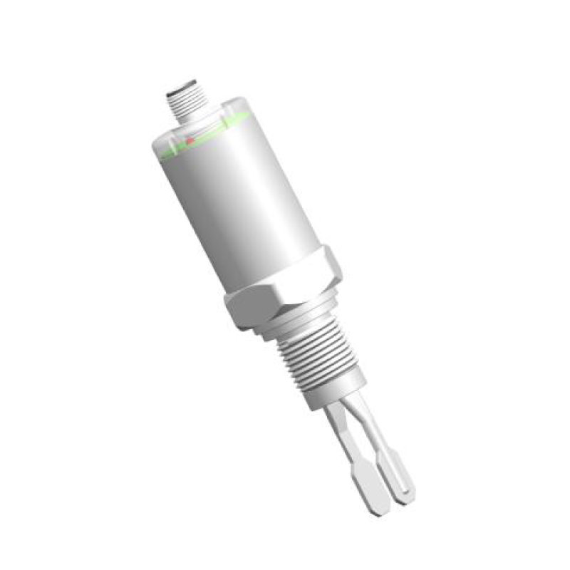
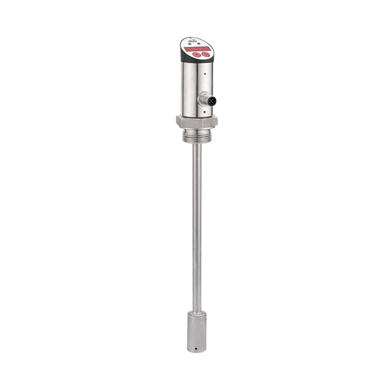
| 3 | Insertion type | ||||||||||||||||||||||||||
| 4 | Clamp type | ||||||||||||||||||||||||||
| Medium | A | Liquid | |||||||||||||||||||||||||
| B | General gas | ||||||||||||||||||||||||||
| C | Saturated steam (temperature and pressure compensation recommended) | ||||||||||||||||||||||||||
| D | Superheated steam (temperature and pressure compensation recommended) | ||||||||||||||||||||||||||
| A thoroughfare | 025 | For calibre options, 025 stands for DN25 pipe (for special pipe (Please consult sales engineer for special diameters) |
|||||||||||||||||||||||||
| Compressive | B | 1.6MPa | |||||||||||||||||||||||||
| C | 2.5MPa | ||||||||||||||||||||||||||
| D | 4.0MPa | ||||||||||||||||||||||||||
| F | Others | ||||||||||||||||||||||||||
| Operating temperature | 1 | Ordinary type: -20-100℃ | |||||||||||||||||||||||||
| 2 | Medium temperature type: 100-250℃ | ||||||||||||||||||||||||||
| 3 | High temperature type: 250-350℃ | ||||||||||||||||||||||||||
| Body Material | 1 | Stainless steel 304 | |||||||||||||||||||||||||
| 2 | Stainless steel 316L | ||||||||||||||||||||||||||
| Flange Material | A | Carbon steel | |||||||||||||||||||||||||
| B | Stainless steel 304 | ||||||||||||||||||||||||||
| C | Stainless steel 316L | ||||||||||||||||||||||||||
| Output signal | 1 | Local display, pulse signal output | |||||||||||||||||||||||||
| 2 | Local display, analogue 4-20mA output | ||||||||||||||||||||||||||
| 3 | No local display, pulse signal output | ||||||||||||||||||||||||||
| 4 | No local display, analogue 4-20mA output | ||||||||||||||||||||||||||
| Communication method | 0... | 0:No communication 1:RS485 communication 2:HART communication |
|||||||||||||||||||||||||
| Converter type | A | Integral type | |||||||||||||||||||||||||
| B | Split type: Separate meter body | ||||||||||||||||||||||||||
| C | Split type: flow totaliser without meter box | ||||||||||||||||||||||||||
| D | Digital processor (optional) | ||||||||||||||||||||||||||
| Explosion-proof requirements | 1... | 1:Normal type 2: Explosion-proof type | |||||||||||||||||||||||||
| Power supply method | D... | D:24V A:24V+battery power supply C:battery power supply | |||||||||||||||||||||||||
| Compensation method | 1 | No | |||||||||||||||||||||||||
| 2 | Temperature compensation | ||||||||||||||||||||||||||
| 3 | Pressure Compensation | ||||||||||||||||||||||||||
| 4 | Temperature and pressure compensation at the same time | ||||||||||||||||||||||||||
| * The selection table is for parameter selection only and is shipped with the corresponding code for the parameter. | |||||||||||||||||||||||||||
Shanghai Kayuan Electronic
Technology Co., Ltd.
Technology Co., Ltd.
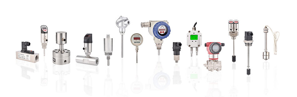
Shanghai Kayuan Electronic Technology Co.,Ltd is an enterprise specializing in the production and R & D of industrial sensors and controllers. Its main products include switches and sensors for flow, pressure, temperature, and liquid level. Intelligent Vortex Flow Sensor-SN53 Suppliers in China.
In 2008, our assembly plant was established in Shanghai China,PAKU INTELLIGENT EQUIPMENT(SHANGHAI)CO.,LTD a subsidiary of Kayuan to produce the PAKU series of products. As Intelligent Vortex Flow Sensor-SN53 Factory, PAKU products are now widely used in different industries, including automation complete sets of equipment, petroleum equipment, chemical equipment, power equipment, welding equipment, steel equipment, metallurgical equipment, automobiles, and water treatment. We adopt advanced technology and manufacturing processes across the board. With our professional design and production technology, comprehensive product lines, excellent quality, and sales network services, we can not only provide users with timely and professional technical support but also offer high - quality one - stop services.
We have served many customers at home and abroad, and offer Intelligent Vortex Flow Sensor-SN53 Wholesale, our products are sold to countries such as Canada, the United States, Brazil, Indonesia, Vietnam, Thailand, and Russia. We welcome extensive cooperation with OEM and ODM customers.

information
 [email protected]
![]() +86-13386111894 / +86-021-37566990
+86-13386111894 / +86-021-37566990
![]() B-4th Floor, Lane 1313, Nanting Road, Nanqiao Town, Fengxian District, Shanghai, China
B-4th Floor, Lane 1313, Nanting Road, Nanqiao Town, Fengxian District, Shanghai, China

Product Links