

 +86-13386111894
 Products & Solutions
 en
 English
 Русский
 España
 عرب .
If you need any help, please feel free to contact us
inquire
How a Pressure Transmitter Works: From Diaphragm Deflection to a 4-20 mA Signal
The Short Answer: Pressure In, Current Out
Power a two-wire pressure transmitter with 24 VDC and put a milliamp meter in the loop. At zero pressure you will read close to 4 mA; at the top of the configured range you will read 20 mA. Everything inside the housing exists to make that sentence true: a sensing element that changes physically when pressure changes, a circuit that turns that change into a stable current, and a housing that keeps the process fluid away from both.
So the answer to how a pressure transmitter works is really two answers stacked on top of each other. The first is material science: how pressure bends a diaphragm, compresses a crystal, or shifts a capacitor plate. The second is electronics: how a tiny change in resistance or capacitance becomes a 4-20 mA signal that a PLC, recorder, or DCS can read reliably over hundreds of meters of cable.
Knowing which stage is failing also decides how you troubleshoot. A transmitter sitting flat at 4 mA while the process is clearly pressurized usually has a blocked impulse line or a dead sensing element, not a software fault. A reading that is stable but consistently shifted by 0.3 bar points at zero drift, mounting stress, or a wet reference side.
Stage One: Turning Pressure Into a Measurable Physical Change
The process connection exposes one side of a thin diaphragm, capsule, or piston to the medium. Pressure pushes it, and the deflection is small, often only micrometers at full scale. The sensing element's job is to convert that movement into an electrical property that can be measured cleanly: resistance, capacitance, or charge.
Piezoresistive and Diffused Silicon
In a diffused silicon element, four strain gauges are formed directly into a silicon diaphragm and wired as a Wheatstone bridge. As the diaphragm flexes, two gauges stretch and two compress, unbalancing the bridge. The raw output is a millivolt-level differential signal, typically tens of millivolts at full scale and proportional to pressure. This is the workhorse technology in general-purpose industrial transmitters because it is compact, repeatable, and linear across a wide range.PN502 Diffused Silicon Pressure TransmitterCompact diffused silicon transmitter for harsh environments, with a wide 0...600 bar range, fast response, and use in machinery, hydraulics and pressure control.View Product →
Ceramic and Capacitive Elements
Ceramic piezoresistive sensors use a thick-film bridge printed onto a ceramic diaphragm. The ceramic body tolerates many aggressive media and handles overpressure gracefully, which is why it appears often in process and utility duty. Capacitive elements take a different route: the diaphragm itself becomes one plate of a capacitor, and deflection changes the gap and therefore the capacitance. Capacitive designs shine at very low differential pressures, such as filter monitoring, clean rooms, and air handling.
Single-Crystal Silicon
Single-crystal silicon elements use a bonded or etched silicon structure that reduces hysteresis and long-term drift compared with some glued or thick-film assemblies. Where the measurement feeds custody transfer, blending ratios, or a safety interlock, that extra stability usually justifies the cost difference. If you are still deciding which family suits a given duty, this overview of pressure sensor types, applications, and selection criteria walks through the trade-offs in more detail.

Stage Two: From Millivolts to a 4-20 mA Loop
The bridge output is far too small and too fragile for a plant floor, and it drifts with temperature. Signal conditioning fixes both problems in a fixed sequence:
- Excitation: a regulated voltage or current feeds the bridge so the output depends on pressure alone, not on supply variation.
- Amplification and temperature compensation: the millivolt signal is amplified, while an internal temperature sensor drives correction circuits that offset the thermal drift of both the element and the electronics.
- Linearization: the corrected signal is shaped into a straight line across the configured range, usually through a digital correction table in modern transmitters.
- Voltage-to-current conversion: the final stage drives a loop current proportional to pressure, normally 4 mA at the lower range value and 20 mA at the upper range value.
The 4-20 mA convention survived for a simple reason: current is unaffected by cable resistance. A voltage signal sags over a long run, while a current loop reads the same at 10 m or 500 m as long as total loop resistance stays within the transmitter's limit. The live zero matters too. Because 4 mA represents zero pressure rather than 0 mA, the receiving device can distinguish a genuine zero reading from a broken wire or a failed transmitter.
Sensing Technologies Side by Side
| Element | How it responds | Where it fits | Practical caution |
| Diffused silicon | Strain gauges diffused into a silicon diaphragm unbalance a bridge | General process, hydraulics, pneumatics, OEM equipment | Media compatibility depends on the isolating diaphragm and fill fluid |
| Ceramic piezoresistive | Thick-film bridge printed on a ceramic diaphragm | Aggressive media, utility and process duty with overpressure risk | Lower full-scale sensitivity at very small ranges |
| Capacitive | Diaphragm deflection changes the capacitance gap | Low differential pressure, filter and airflow monitoring | Sensitive to moisture ingress and reference-side contamination |
| Single-crystal silicon | Etched or bonded silicon structure with low mechanical stress | High-accuracy, custody transfer, safety-related loops | Higher purchase cost; needs a clean, well-matched installation |
| Piezoelectric | Charge generated by dynamic strain only | Fast pressure pulses, vibration and dynamic test benches | Cannot hold a steady static reading |
No row in that table is universally "best." The correct choice follows the medium, the range, the required stability, and how the measurement will be used downstream.
Gauge, Absolute, and Differential: The Reference Point Changes Everything
The sensing element only knows the difference between the pressure on its front face and whatever sits on the other side. That "whatever" defines the measurement type:
- Gauge: the back of the diaphragm is vented to atmosphere, so the reading is pressure above local ambient. This is the default for pumps, compressors, and most utility loops.
- Absolute: the reference is a sealed vacuum, so the reading is true pressure above zero. Used for vacuum processes, barometric work, and sealed vessels where ambient changes would corrupt the result.
- Differential: both sides are plumbed to process, and the output is the difference between them, as measured across a filter, orifice plate, or heat exchanger.
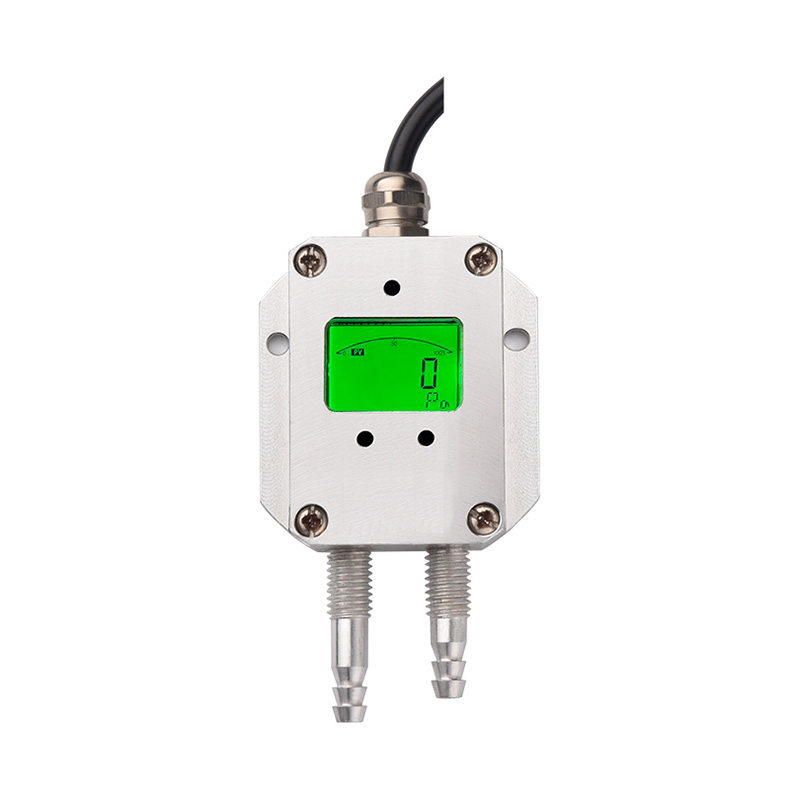
This is where installation errors start. A gauge transmitter with a blocked or water-filled vent will read wrong in a way that looks exactly like a calibration shift. A differential unit with a mismatched impulse line will report a difference that does not exist. Selecting the right reference type, and the right housing for the environment, matters more than squeezing the last decimal out of the accuracy specification.PN55 Micro Differential Pressure Transmitter for AirPanel-mounted micro differential pressure transmitter for air with FND display and multiple outputs, suited to low-pressure monitoring.View Product →
Two-Wire, Three-Wire, and Four-Wire: What the Wiring Tells You
Count the conductors and you can usually predict the architecture. Two-wire transmitters are loop-powered: the same pair carries power and signal, the current is the signal, and 4 mA is the minimum current needed to keep the electronics alive. Three-wire units typically have separate power and signal grounds with a 0-10 V or 0-5 V output. Four-wire units have independent supply and output circuits, which allows higher power consumption for local displays, heavy HART polling, or heated housings in cold climates.
Check the loop budget before assuming a two-wire device will work. Total resistance from supply to receiver must stay below the transmitter's maximum load, which is usually plotted against supply voltage. A 250 ohm input card, plus cable resistance, plus an intrinsic safety barrier can push past that limit and cause the reading to fold back near the top of the range. The symptom looks like a calibration fault but is really an Ohm's law problem.
Where Accuracy Is Actually Lost
Most field error does not come from the element. It comes from the installation and the environment around it:
- Impulse lines: trapped gas in a liquid line, or condensate in a gas line, adds a hydrostatic offset that no calibration can remove.
- Temperature: ambient swings shift both the electronics and the fill fluid. Check the total error band over temperature, not just the reference accuracy at 25 degrees Celsius.
- Mounting stress: over-torquing a low-range transmitter, or compressing the wrong gasket, bends the housing and shifts zero.
- Overpressure events: water hammer and pump start-up spikes can permanently offset a diaphragm. A stated burst pressure is not the same as a recoverable limit.
- Electrical noise: variable frequency drives and poor grounding inject ripple into the loop. Shielded twisted pair, grounded at one end, remains the cheapest fix.
Distinguish zero drift from span drift before you adjust anything. Zero drift is a constant offset across the range; span drift changes the slope. Trimming zero to hide a span problem will push the error to the other end of the scale.
What to Confirm Before You Specify or Replace One
- Reference type: gauge, absolute, or differential, and whether the reference side needs a vent, a seal, or a second connection.
- Range and turndown: size the upper range value at roughly 1.5 to 2 times normal working pressure. Choosing a 100 bar unit for a 6 bar line costs you resolution for no benefit.
- Wetted materials and seals: match the isolating diaphragm, process connection, and gasket to the medium, especially with corrosive, viscous, or sanitary duty.
- Output and loop compatibility: 4-20 mA, HART, or voltage, plus the loop load and supply voltage you actually have.
- Environment: hazardous area classification, ingress protection, vibration, and washdown requirements.
- Accuracy statement: ask for the total error band including temperature effects, long-term stability, and mounting position, not the headline reference figure alone.
A transmitter that is specified correctly is a boring component. It sits on the line for years, returns the same current for the same pressure, and never appears on a maintenance list. That outcome comes from matching the sensing element, the reference type, and the loop design to the actual process, rather than from any single specification number.PN30C High-Precision Single Crystal Silicon Pressure TransmitterHigh-precision monocrystalline silicon transmitter with isolated circuitry, data backup and external zero adjustment, designed for stable liquid, gas and steam pressure measurement.View Product →
PREV: How Does a Pt100 Work? Platinum Resistance, Wiring, and Accuracy Explained It is the last article
information
 [email protected]
 +86-13386111894 / +86-021-37566990
[email protected]
 B-4th Floor, Lane 1313, Nanting Road, Nanqiao Town, Fengxian District, Shanghai, China

Product Links