 en
en English
 Русский
 España
 عرب .
عرب .

If you need any help, please feel free to contact us
inquire
If you have any further questions, please call +86-021-37566990 or fill out the inquiry form.
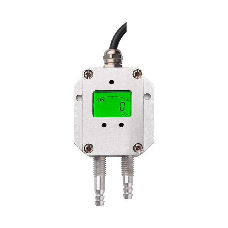
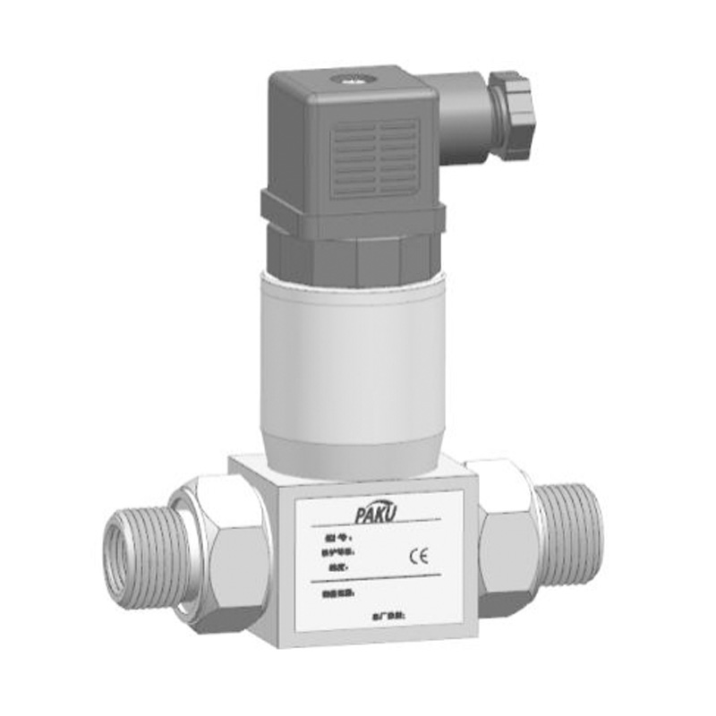
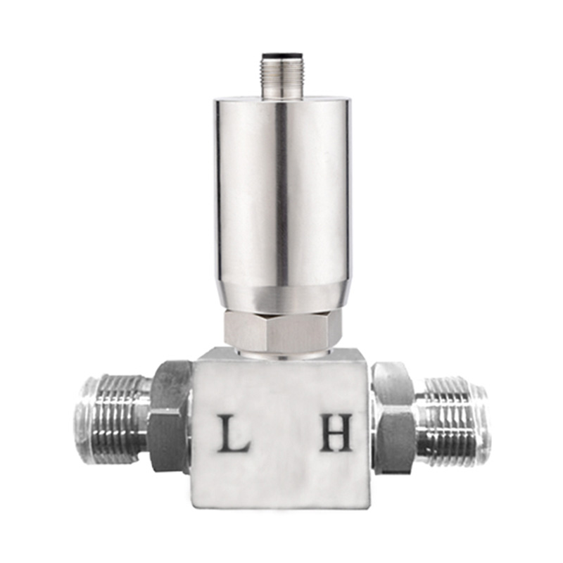
Product 3D Image Get couponsCompact differential pressure transmitter-PN51
Product introduction
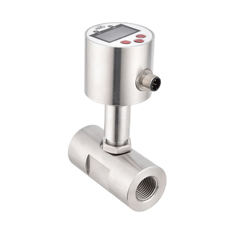
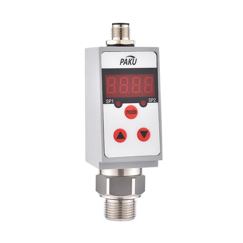
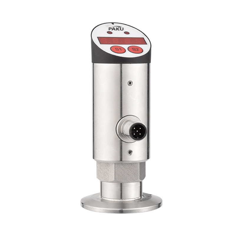
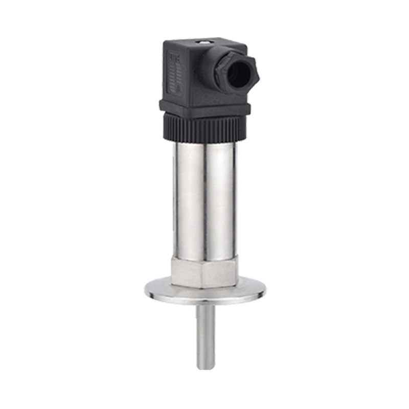
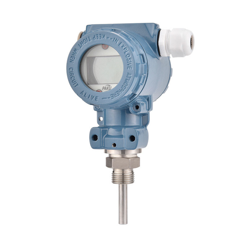
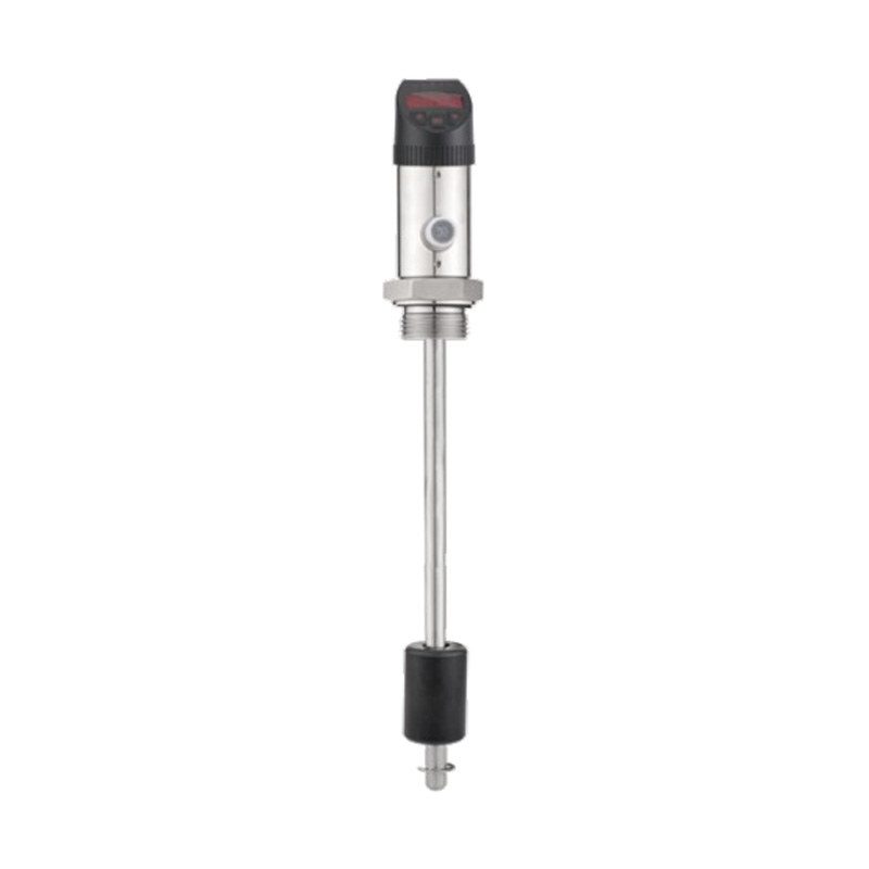
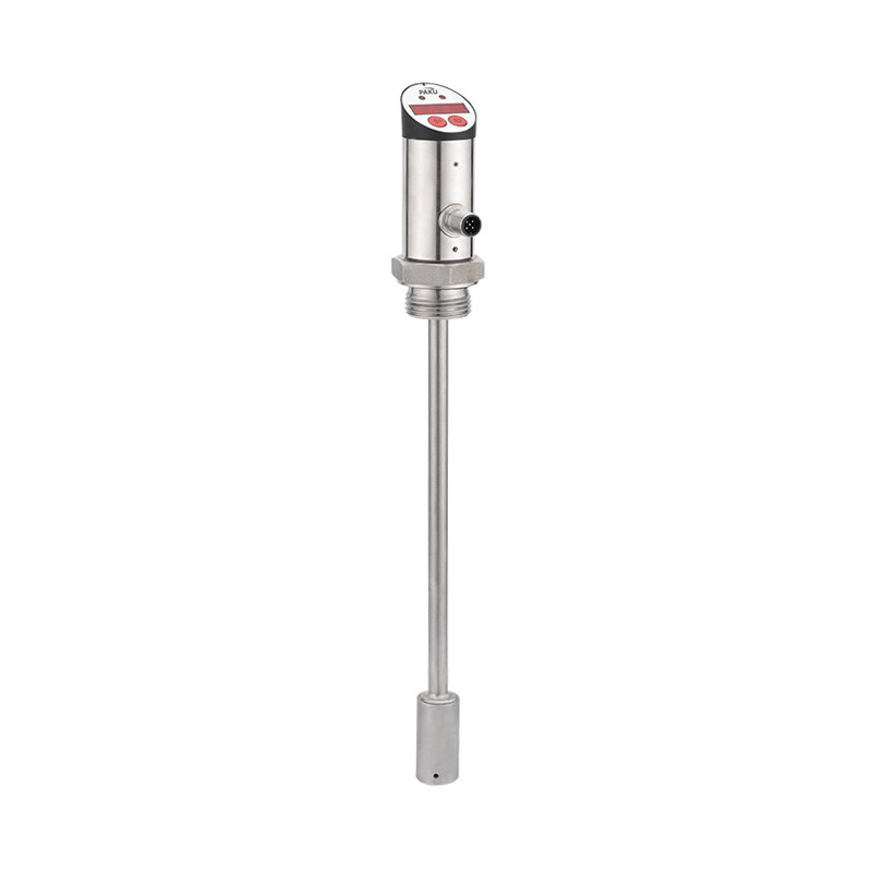
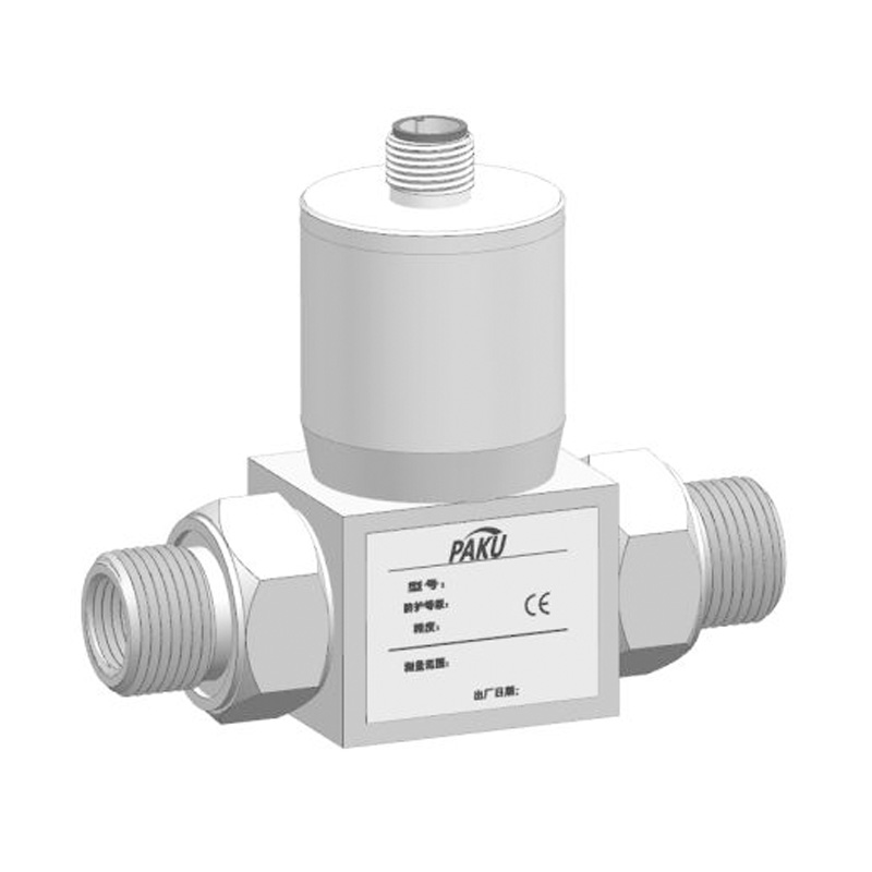
PN51 series diffused silicon differential pressure transmitter is composed of double isolation differential pressure sensor and integrated amplifier circuit, which has the advantages of high stability and good dynamic measurement performance. It is equipped with high-performance microprocessor to correct and compensate sensor nonlinearity and temperature drift, realize accurate digital data transmission, field equipment diagnosis, remote two-way communication and other functions, suitable for use in the measurement and control of liquid and gas. This transmitter has a variety of range, can meet the needs of all kinds of users. It is widely used in metallurgy, machinery, petroleum, chemical industry, power station, light industry, food, environmental protection, national defense and scientific research in various fields.
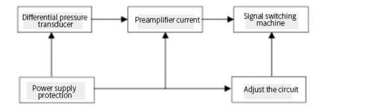
The working principle of diffused silicon differential pressure transmitter is: the process pressure acts on the sensor, the sensor is the output voltage signal proportional to the pressure, the voltage signal is transformed into 4-20mA standard signal through the amplifier circuit. The power supply protection circuit provides excitation for the sensor, and the sensor adopts precision temperature compensation circuit. Its working principle block diagram is as follows:
Technical Specification
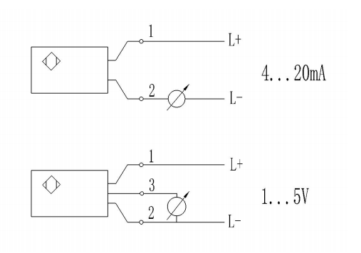
Wiring Diagram
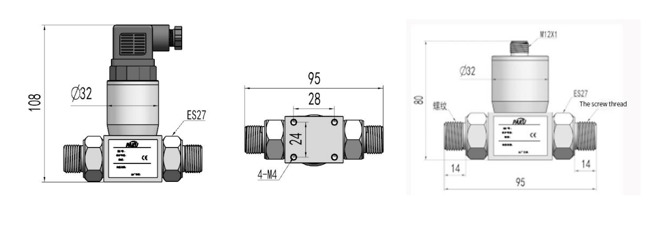
Size Chart
Selection Table
Notes
| range ability | 0... 0.2 bar to zero... 35bar | ||||||
|
accuracy |
±0.5% | ||||||
| power supply | 24VDC(10-30)VDC | ||||||
| signal output | 4-20mA DC | ||||||
| long-term stability | Plus or minus 0.2% or less F.S/year | ||||||
| over load pressure | ≤ 3 times of rated pressure | ||||||
| operating temperature range |
( -20~80 )℃ | ||||||
| size of interface | customizable | ||||||
| PN51- | ... | A | G4 | H | 1 | specification | |||||
| PN51- | PN51 series exquisit | ||||||||||
| ... | Range: 0... 0.2 bar to zero... 35bar (user customizable) |
||||||||||
| A | Output: 4-20 ma | ||||||||||
| B | Output: 0 to 5v | ||||||||||
| C | Output: 1-5 v | ||||||||||
| D | Output: 0 to 10v | ||||||||||
| G4 | Interface thread: G1/4 | ||||||||||
| G2 | Interface thread: G1/2 | ||||||||||
| N4 | Interface thread: NPT1/4 | ||||||||||
| H | RA | ||||||||||
| K | RI | ||||||||||
| 1 | Hersman joint | ||||||||||
| 2 | M12 x 1 connector | ||||||||||
| * The selection table is only available for parameter selection, and the corresponding code is delivered. | |||||||||||
- Differential pressure transmitter is small in size and light in weight. It can be installed directly on the measuring point during installation. Pay attention to check the sealing of the pressure interface to prevent the impact of air leakage on the measurement accuracy.
- According to the provisions of the wire connection, the transmitter can enter the working state. When the measurement accuracy is high, the instrument should be energized for half an hour before entering the working state.
- The differential pressure transmitter is recommended to be installed with a two-way valve to prevent excessive static pressure at both ends of the transmitter.
- Differential pressure transmitters shall be used in gases and liquids that are not corrosive to 316L stainless steel diaphragms.
- Wiring should be in strict accordance with the instructions to ensure the normal operation of the transmitter.
- The shielded cable can be used when the field interference is larger or the requirements are higher.
Shanghai Kayuan Electronic
Technology Co., Ltd.
Technology Co., Ltd.
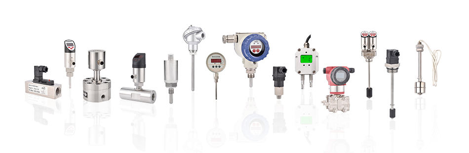
Shanghai Kayuan Electronic Technology Co., Ltd is an enterprise specializing in the production and R&D of industrial fluid sensors and controllers. Its main products include switches and sensors for flow, pressure, temperature, and liquid level.
In 2008, our assembly plant was established in Shanghai, China, to produce the PAKU series of products. We adopt advanced technology and manufacturing processes across the board. With our professional design and production technology, comprehensive product lines, excellent quality, and sales network services, we can not only provide users with timely and professional technical support but also offer high - quality one - stop services.
The company has set up various departments such as the purchasing department, R & D department, quality management department, finance department, sales department, after - sales department, general office, laboratory, archive room, calibration workshop, production workshop, inspection area, storage area, shipping area, and a tea break room, aiming to provide products of excellent quality and sincere services.
We adhere to the customer - centric concept of creating value for customers. According to the industry needs of customers, we continuously update technology and optimize services, aiming to become a leader in the field of process automation.
PAKU products are now widely used in different industries, including automation complete sets of equipment, petroleum equipment, chemical equipment, power equipment, welding equipment, steel equipment, metallurgical equipment, automobiles, and water treatment. We have served many customers at home and abroad, and our products are sold to countries such as Canada, the United States, Brazil, Indonesia, Vietnam, Thailand, and Russia.
In the increasingly competitive global market in the future, PAKU will, as always, serve a wide range of domestic and foreign customers with excellent quality, reasonable and competitive prices, on - time delivery, and perfect after - sales service. We welcome extensive cooperation with OEM and ODM customers.
information
 [email protected]
![]() +86-13386111894 / +86-021-37566990
+86-13386111894 / +86-021-37566990
![]() 4th Floor, No. 3, Lane 1313, Nanting Road, Fengxian District, Shanghai China
4th Floor, No. 3, Lane 1313, Nanting Road, Fengxian District, Shanghai China

Product Links