 en
en English
 Русский
 España
 عرب .
عرب .

If you need any help, please feel free to contact us
inquire
If you have any further questions, please call +86-021-37566990 or fill out the inquiry form.
Get coupons PDF DownloadCable float level switch-LF900
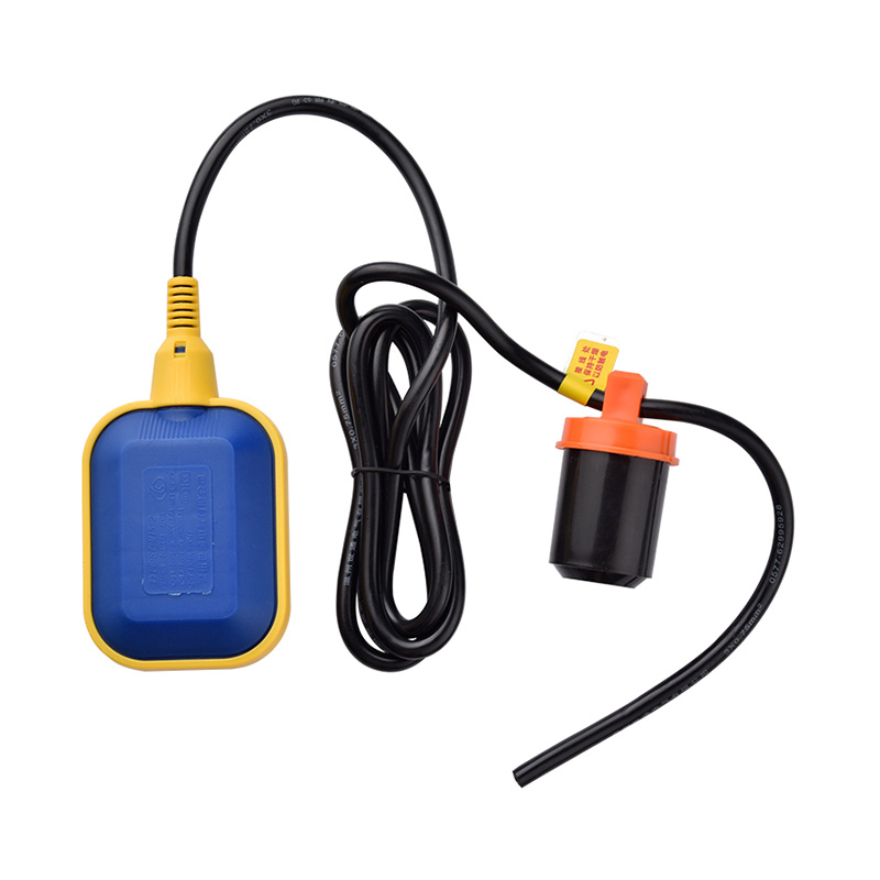
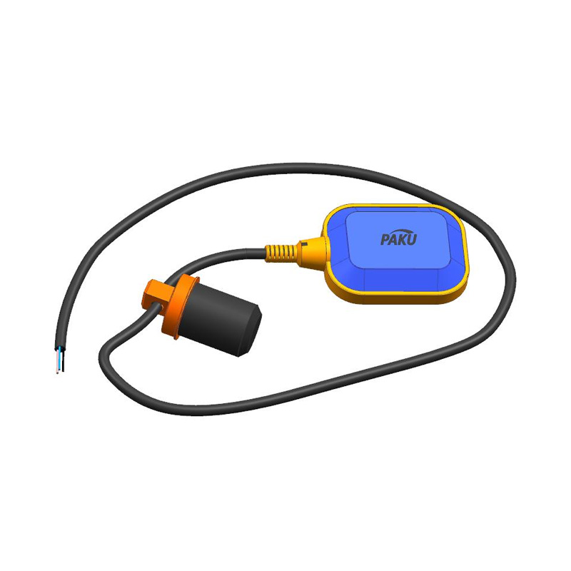
Product introduction
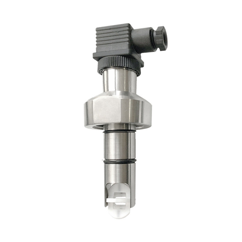
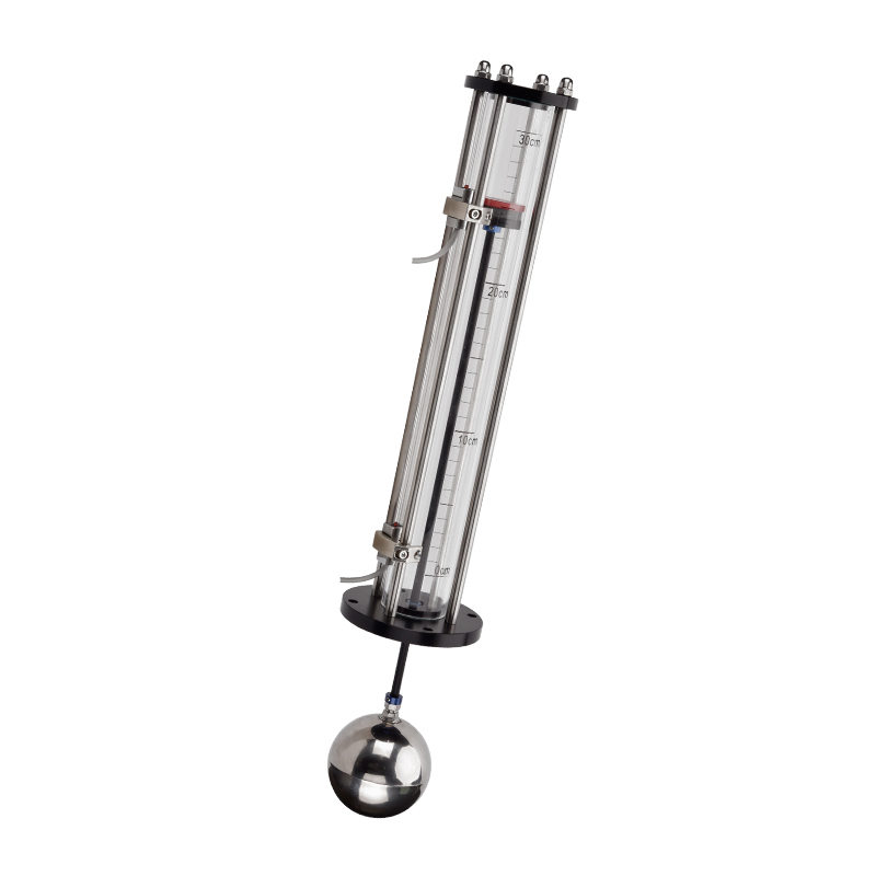
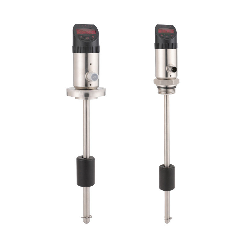
Cable float ball level controller, using the principle of gravity and buoyancy design. It mainly comprises a floating body, a large capacity micro-switch set in the floating body and a driving mechanism that can switch in the on-off state, and a three-core cable connected with the switch. When the float ball under the action of liquid buoyancy with the rise or fall to the level of a certain Angle, the floating ball body drive mechanism -- drive large capacity micro switch, so as to output ON (ON) or OFF (OFF) signal, a total of alarm prompt or remote control use.
- Imported patented integrated plastic injection molding (PP), or compressed nut and silicone joint sealing (SUS);
- simple and reasonable structure, stable and reliable performance;
- installation and use is very convenient, simple on-site adjustment;
- can be used with a variety of pumps, and widely used in water supply and drainage and containing corrosion, suspended substance automatic control levelproduct application It is mainly used in household, factory and mine water tank, oil, acid and alkali pool, barrel, tank, irrigation container, etc.
Technical Specification
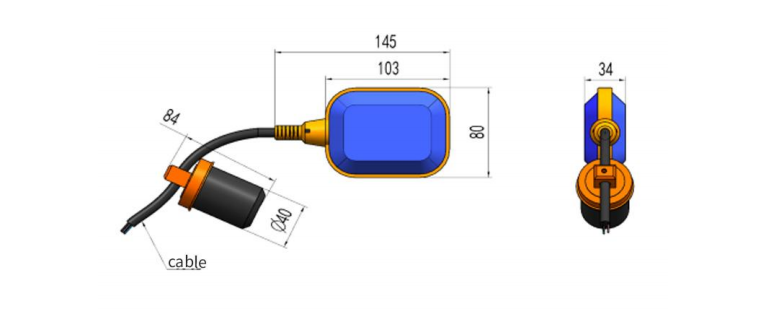
Dimension Figure
Selection Table
Installation And Wiring Mode
- Working pressure: one atmosphere
- Operating temperature: -10~80 degrees (PP), -10~180 degrees (metal)
- rated current :10A/220V ,SPDT( PP ),2A/220V,SPDT ( SUS )
- contact capacity:15A/250VAC
- Switch life:1 million times
- PTFE:PP ,SUS
- Control accuracy: ±0.05m
- Applicable medium: water, sewage, oil and medium concentration of the following acid and alkali liquid
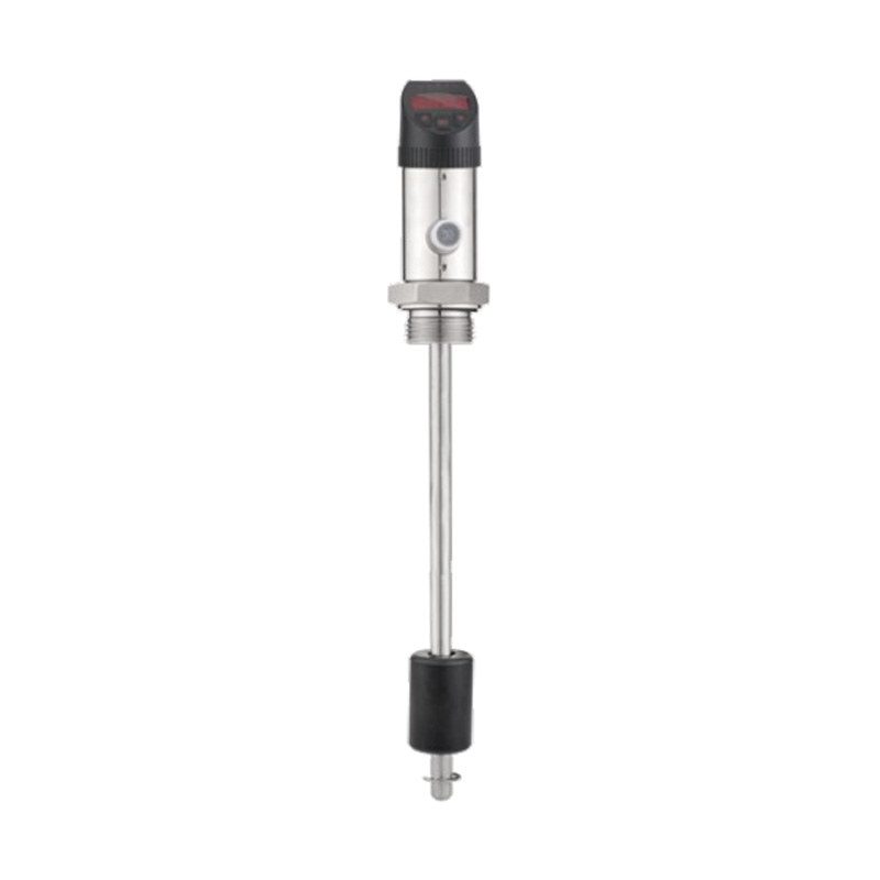
- Cable length: 5m / 10m (special length can be customized)
- Connection: directly drop line or add flange and junction box- Imported patented integrated plastic injection molding (PP), or compressed nut and silicone joint sealing (SUS);
- simple and reasonable structure, stable and reliable performance;
- installation and use is very convenient, simple on-site adjustment;
- can be used with a variety of pumps, and widely used in water supply and drainage and containing corrosion, suspended
substance automatic control levelproduct application It is mainly used in household, factory and mine water tank, oil, acid and alkali pool, barrel, tank, irrigation container, etc.
| Selection table | |||||||||||
| LF900- | A | 1 | A | specification | |||||||
| LF900- | LF900 series wireline float level switches | ||||||||||
| A | Liquid material: PP+ rubber cable | ||||||||||
| B | Liquid connection material: SUS+ silicone cable | ||||||||||
| 1 | No wiring box | ||||||||||
| 2 | Common junction box (when installed with flange) | ||||||||||
| 3 | Explosion-proof junction box (when installing with flange) | ||||||||||
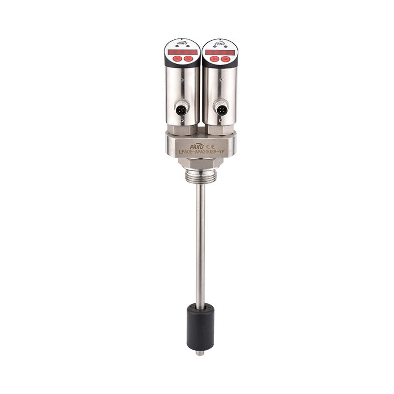
| A | single | ||||||||||
| B | group | ||||||||||
| X | Units: a | ||||||||||
| XX | unit:m | ||||||||||
| * The selection table is only available for parameter selection, and the corresponding code is delivered. | |||||||||||
1. Run the float switch wire through the plastic hammer.
2. Use the plastic buckle to fix the hammer on the wire at the position to set the water level.
3. Pull the wire to the control box, try to avoid the use of intermediate joints, if a joint is needed, do not immerse the joints in the liquid.
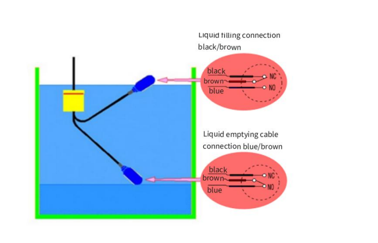
- Use brown and black wire:
When the float ball is at the liquid level, the contact is closed.
When the float is on the liquid level, the contact point is in the open state.
- Use blue and brown wires:
When the float is on the liquid level, the contact point is blocked.
When the float ball is at the liquid level, the contact point is in the open state.
- The following figure is the schematic diagram of the micro-switch inside the floating ball when the PP material cable floating ball level switch is working:
When the liquid level is at the lower side of the buoy body, the buoy droops, the brown line (collinear COM) and the black line (normally open NC) are in the disconnected state, and the brown line and the blue line (normally closed NO) are in the connected state.
When the liquid level rises, the buoy follows and rises by about 28 degrees (SUS material switch is about 10 degrees), the brown line closes with the black line, and the brown line disconnects with the blue line. So as to achieve the purpose of control.
When the liquid level drops, the buoy body will follow it down until it is about 28 degrees below the horizontal line (SUS material switch is about 10 degrees), and each control point will resume its initial state.
Shanghai Kayuan Electronic
Technology Co., Ltd.
Technology Co., Ltd.
Shanghai Kayuan Electronic Technology Co.,Ltd is an enterprise specializing in the production and R & D of industrial sensors and controllers. Its main products include switches and sensors for flow, pressure, temperature, and liquid level. Cable float level switch-LF900 Suppliers in China.
In 2008, our assembly plant was established in Shanghai China,PAKU INTELLIGENT EQUIPMENT(SHANGHAI)CO.,LTD a subsidiary of Kayuan to produce the PAKU series of products. As Cable float level switch-LF900 Factory, PAKU products are now widely used in different industries, including automation complete sets of equipment, petroleum equipment, chemical equipment, power equipment, welding equipment, steel equipment, metallurgical equipment, automobiles, and water treatment. We adopt advanced technology and manufacturing processes across the board. With our professional design and production technology, comprehensive product lines, excellent quality, and sales network services, we can not only provide users with timely and professional technical support but also offer high - quality one - stop services.
We have served many customers at home and abroad, and offer Cable float level switch-LF900 Wholesale, our products are sold to countries such as Canada, the United States, Brazil, Indonesia, Vietnam, Thailand, and Russia. We welcome extensive cooperation with OEM and ODM customers.
information
 [email protected]
![]() +86-13386111894 / +86-021-37566990
+86-13386111894 / +86-021-37566990
![]() B-4th Floor, Lane 1313, Nanting Road, Nanqiao Town, Fengxian District, Shanghai, China
B-4th Floor, Lane 1313, Nanting Road, Nanqiao Town, Fengxian District, Shanghai, China

Product Links