 en
en English
 Русский
 España
 عرب .
عرب .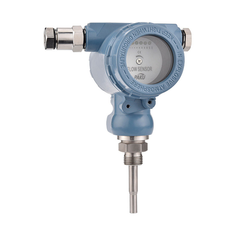

If you need any help, please feel free to contact us
inquire
If you have any further questions, please call +86-021-37566990 or fill out the inquiry form.
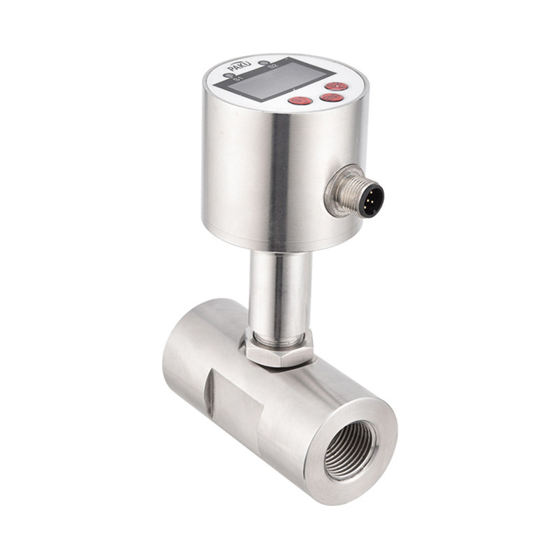
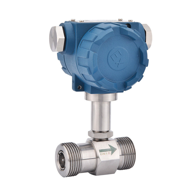
Get coupons PDF DownloadTurbine Flow Sensor-SN51
Product introduction
SN51 series turbine flow sensor is a precision flow measuring instrument. It absorbs advanced technology of domestic and foreign flow instruments and has been optimized and designed. It has a simple structure, lightweight and
It has high accuracy, good reproducibility, sensitive response, easy installation, maintenance and use, and is suitable for measuring low viscosity media such as water, diesel, gasoline, etc. Compatibility with corresponding traffic
The instrument case matching can be used to measure the flow rate and total amount of liquid. Widely used in computing and control systems in petroleum, chemical industry, metallurgy, scientific research and other fields.
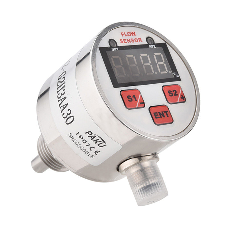
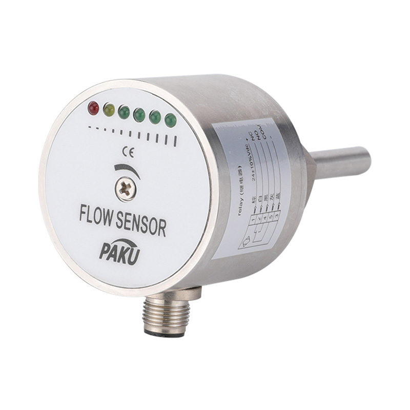
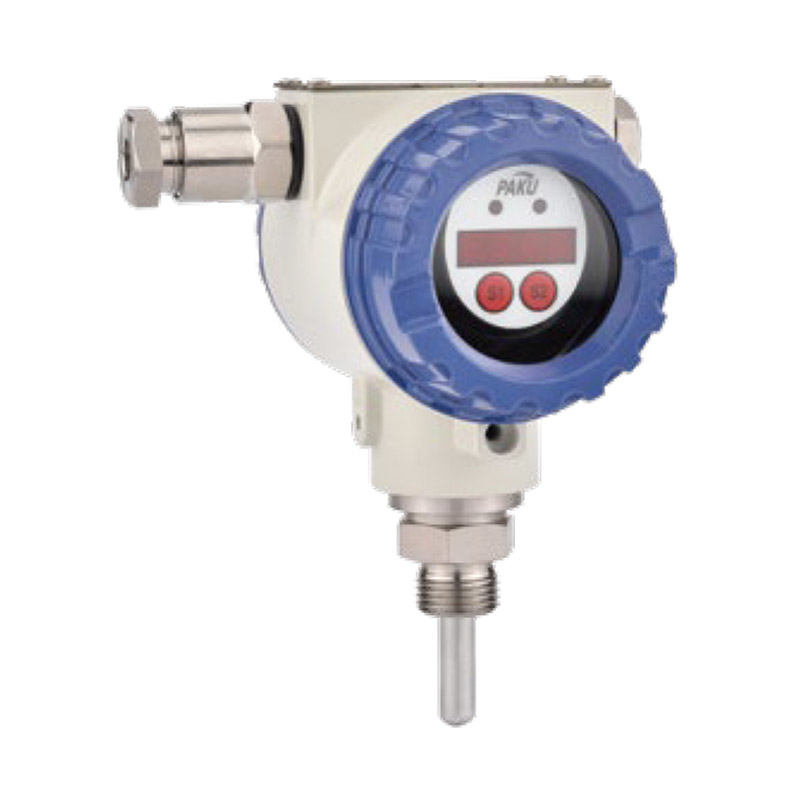
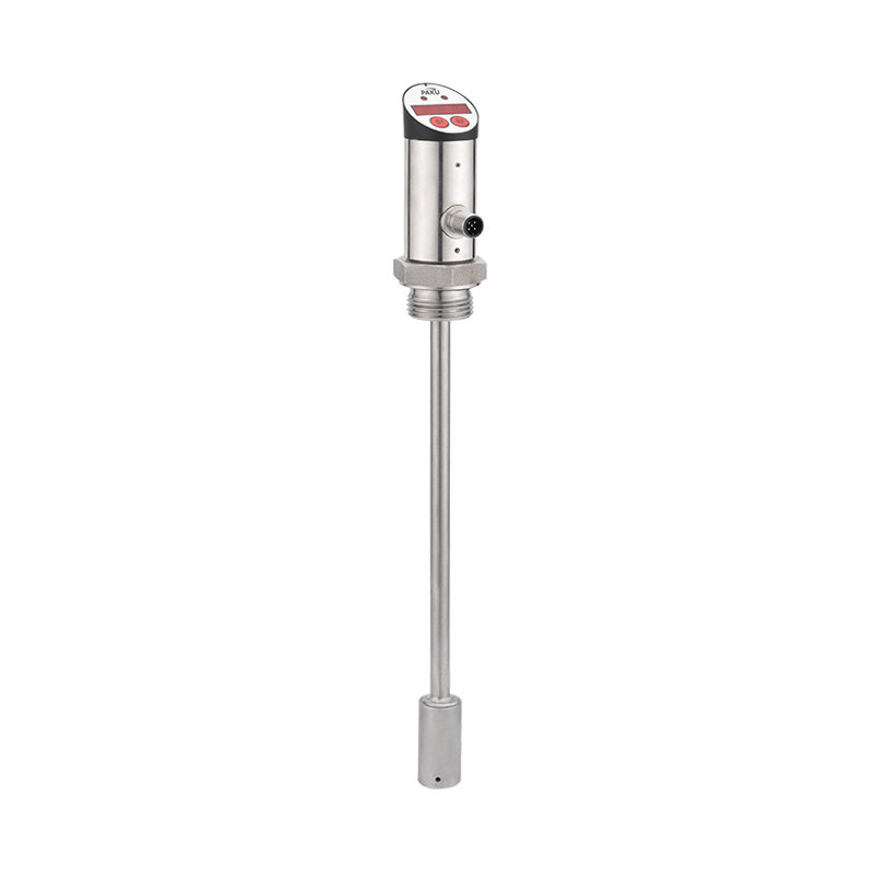
Sensors are available in various forms such as ordinary type, high-precision type and wear-resistant type (cemented carbide). There are two types of amplifiers: ordinary type and explosion-proof type, and the sensor can also be calculated with on-site flow.
The meter is equipped with (powered by lithium batteries, battery replacement in 1 year).
Parameter Table
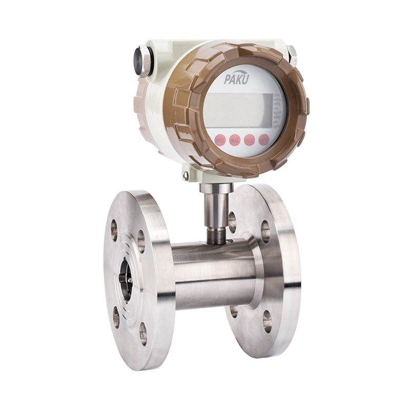
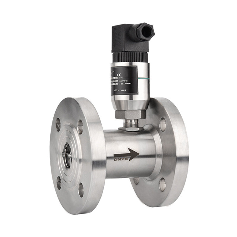
Dimension Drawing
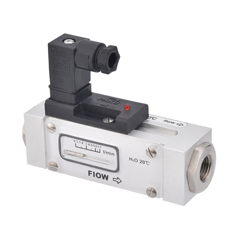
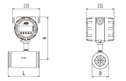
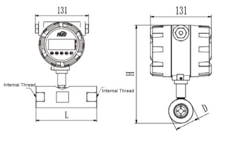
Dimensions 1 (Clip-Fitting Type)
Dimensions Figure 2 (Threaded Connection Type)
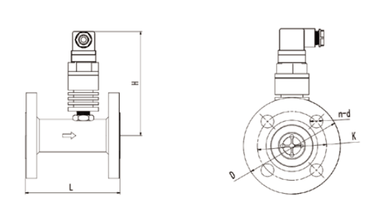
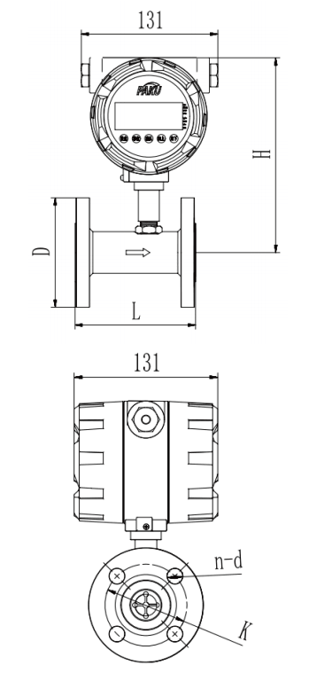
Dimensions Figure 3 (PN16 flange connection type)
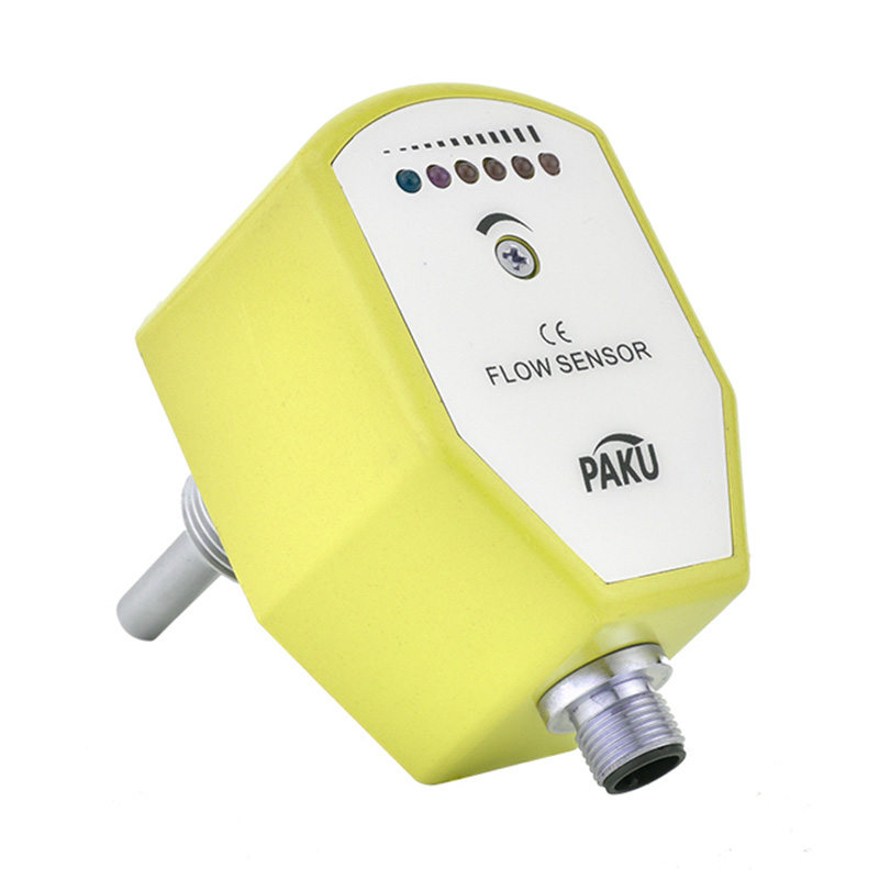
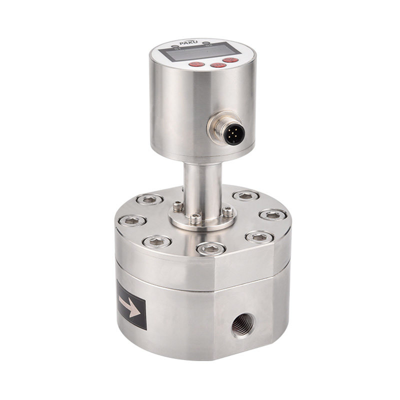
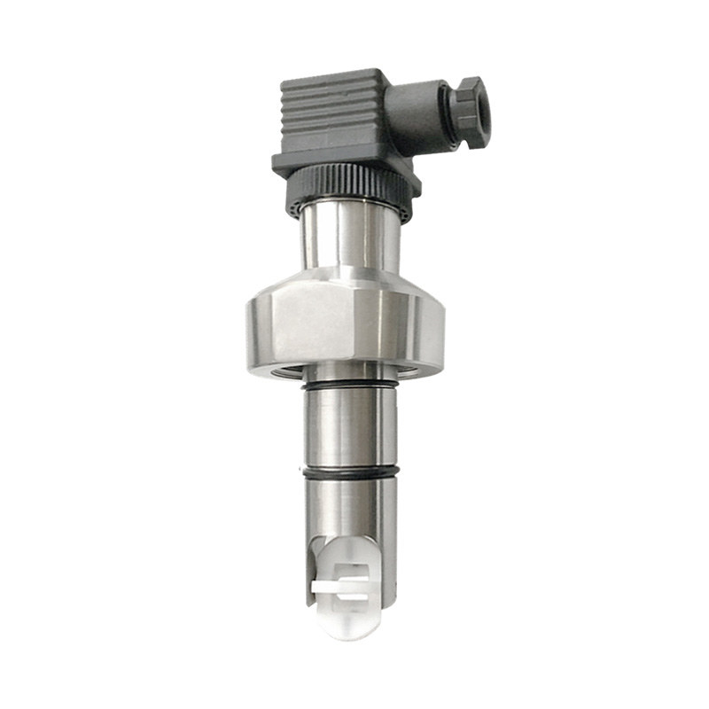
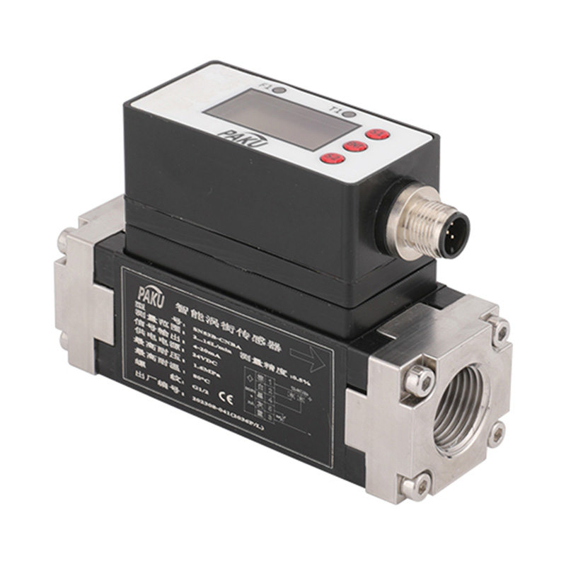
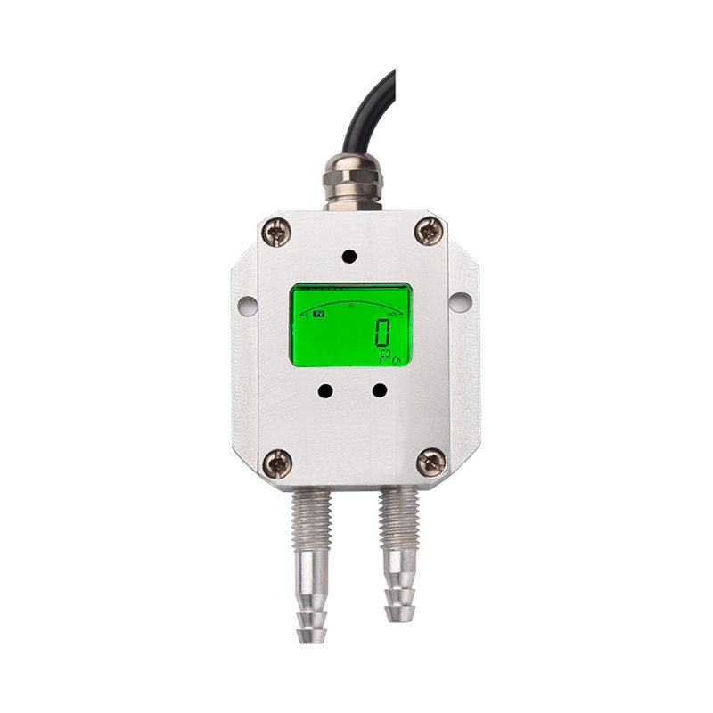
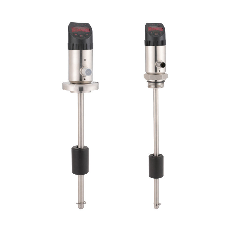
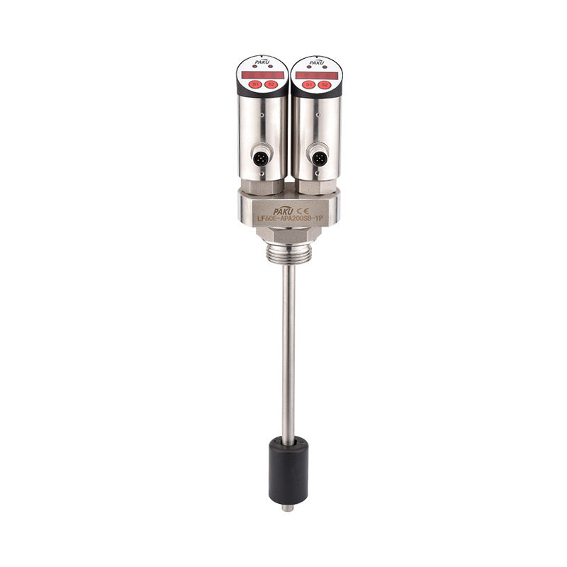
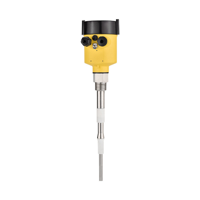
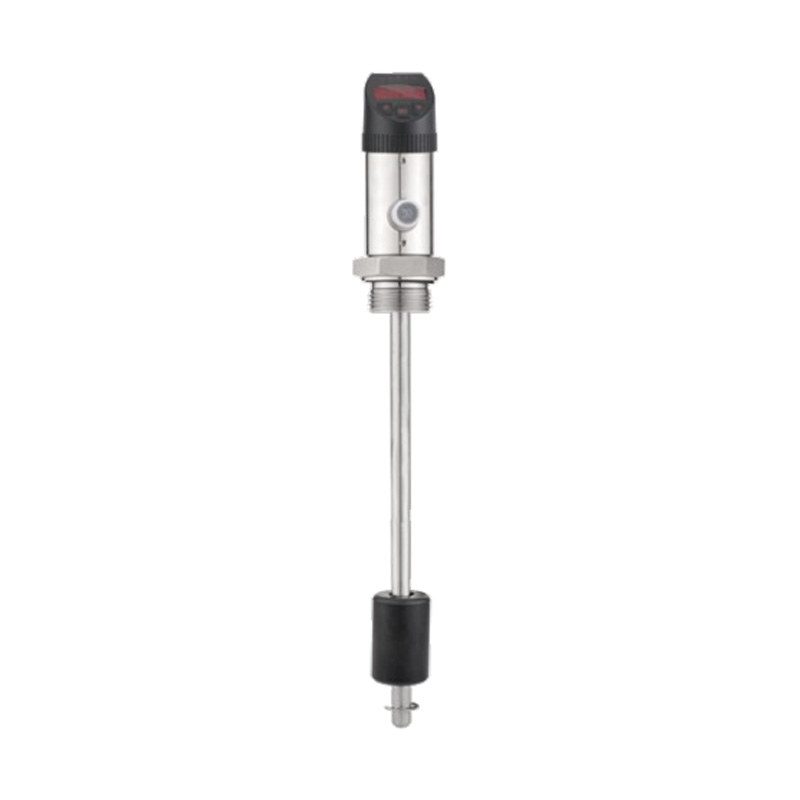
Picture
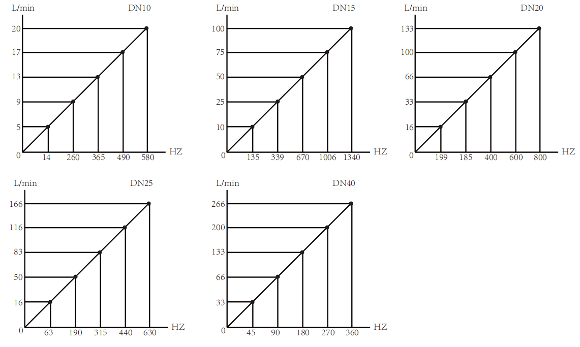
Curve Graph
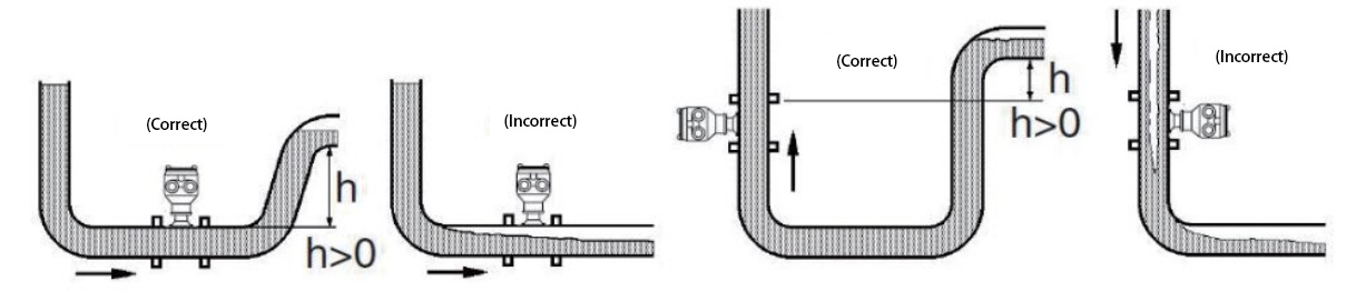
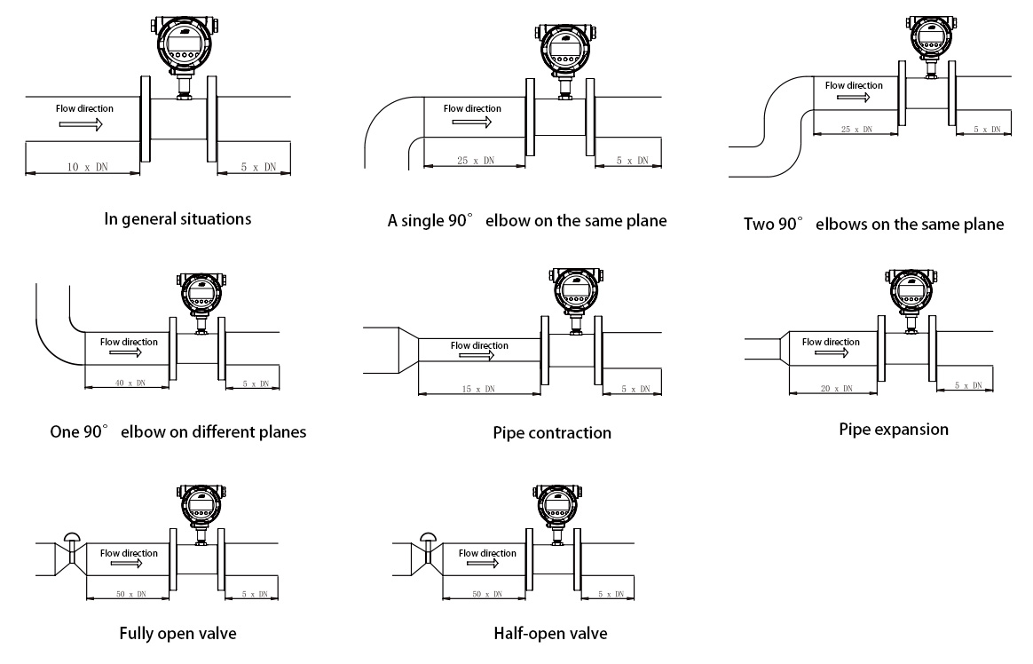
Installation Requirements For Straight Pipe Sections
Selection Table
| Called The Diameter DN( mm ) |
Flow Range( m³/H ) | Nominal Pressure PN(MPa) |
Maximum Pressure Loss (MPa) |
|||||||||||||||||||||||||||||||||
| Lower Limit | Upper Limit | Lower Limit | Upper Limit | Lower Limit | Upper Limit | |||||||||||||||||||||||||||||||
| 2 | 0.03 | 0.16 | Thread pressure resistance: 6.3 Flange pressure resistance: 1.6 Please indicate the special pressure resistance |
0.15 | ||||||||||||||||||||||||||||||||
| 4 | 0.04 | 0.25 | 0.12 | |||||||||||||||||||||||||||||||||
| 6 | 0.1 | 0.6 | 0.08 | |||||||||||||||||||||||||||||||||
| 10 | 0.2 | 1.2 | 0.05 | |||||||||||||||||||||||||||||||||
| 12 | 0.12 | 2.4 | 0.05 | |||||||||||||||||||||||||||||||||
| 15 | 0.6 | 4 | 0.6 | 6 | 0.035 | |||||||||||||||||||||||||||||||
| 20 | 0.8 | 8 | ||||||||||||||||||||||||||||||||||
| 25 | 1.6 | 10 | 1 | 10 | ||||||||||||||||||||||||||||||||
| 32 | 1.5 | 15 | ||||||||||||||||||||||||||||||||||
| 40 | 3 | 20 | 3 | 20 | 2 | 20 | 0.025 | |||||||||||||||||||||||||||||
| 50 | 6 | 40 | 6 | 40 | 4 | 40 | ||||||||||||||||||||||||||||||
| 65 | 8 | 80 | ||||||||||||||||||||||||||||||||||
| 80 | 16 | 100 | 16 | 100 | 10 | 100 | ||||||||||||||||||||||||||||||
| 100 | 25 | 160 | 25 | 160 | 20 | 222 | ||||||||||||||||||||||||||||||
| 125 | 25 | 250 | ||||||||||||||||||||||||||||||||||
| 150 | 60 | 400 | 50 | 300 | 40 | 400 | ||||||||||||||||||||||||||||||
| 200 | 100 | 600 | 80 | 800 | ||||||||||||||||||||||||||||||||
| 250 | 160 | 1000 | 120 | 1200 | ||||||||||||||||||||||||||||||||
| 300 | 260 | 1600 | 180 | 1800 | ||||||||||||||||||||||||||||||||
| Note: The rightmost column of the flow range is the standard reference value, and other flow ranges are customised ranges. | ||||||||||||||||||||||||||||||||||||
Clip-Fitting Type
Flange Connection Type
| Instrument Diameter (mm) |
L (mm) |
D (mm) |
H ( mm) | |||||||||||||||||||||||||||||||||
| Pulse Type | Explosion-Proof Pulse Type | 4-20mA Output Type |
Smart Display | |||||||||||||||||||||||||||||||||
| 15 | 66 | 66 | 155 | 220 | ||||||||||||||||||||||||||||||||
| 20 | 66 | 66 | 160 | 225 | ||||||||||||||||||||||||||||||||
| 25 | 66 | 66 | 165 | 230 | ||||||||||||||||||||||||||||||||
| 32 | 70 | 86 | 170 | 240 | ||||||||||||||||||||||||||||||||
| 40 | 75 | 86 | 180 | 245 | ||||||||||||||||||||||||||||||||
| 50 | 75 | 92 | 195 | 260 | ||||||||||||||||||||||||||||||||
| 65 | 75 | 105 | 205 | 210 | 210 | 275 | ||||||||||||||||||||||||||||||
| 80 | 84 | 120 | 220 | 225 | 225 | 290 | ||||||||||||||||||||||||||||||
| 100 | 90 | 140 | 245 | 250 | 250 | 310 | ||||||||||||||||||||||||||||||
| 125 | 100 | 165 | 270 | 275 | 275 | 340 | ||||||||||||||||||||||||||||||
| 200 | 150 | 240 | 350 | 350 | 350 | 415 | ||||||||||||||||||||||||||||||
| Meter Caliber mm |
External Thread L mm |
Internal Thread L mm |
H( mm) | G External Thread |
G Internal Thread |
||||||||||||||||||
| Pulse Type | Explosion-Proof Pulse Type |
4-20mA Output Type |
Intelligent Display Type |
||||||||||||||||||||
| 4 | 225 | 80 | 142 | 145 | 145 | 210 | G1/2 | G1/4 | |||||||||||||||
| 6 | 225 | 80 | 143 | 145 | 145 | 210 | G1/2 | G1/4 | |||||||||||||||
| 8 | 225 | 80 | 144 | 146 | 146 | 210 | G1/2 | G1/4 | |||||||||||||||
| 10 | 345 | 80 | 145 | 150 | 147 | 210 | G1/2 | G3/8 | |||||||||||||||
| 12 | 345 | 80 | 146 | 150 | 1448 | 212 | G3/4 | G1/2 | |||||||||||||||
| 15 | 75 | 110 | 147 | 150 | 150 | 215 | G1 | G1/2 | |||||||||||||||
| 20 | 85 | 115 | 150 | 155 | 155 | 220 | G1 | G3/4 | |||||||||||||||
| 25 | 100 | 140 | 155 | 160 | 160 | 225 | G1-1/4 | G1 | |||||||||||||||
| 32 | 120 | 168 | 175 | 180 | 180 | 245 | G1-1/2 | G1-1/4 | |||||||||||||||
| 40 | 140 | 180 | 180 | 184 | 180 | 250 | G2 | G1-1/2 | |||||||||||||||
| 50 | 150 | 200 | 185 | 190 | 190 | 255 | G2-1/2 | G2 | |||||||||||||||
| Note: The above DN4-DN10 flow sensor includes the factory-standard straight pipe section size, DN15-DN50 Diameter flow sensor does not include straight pipe section size |
|||||||||||||||||||||||
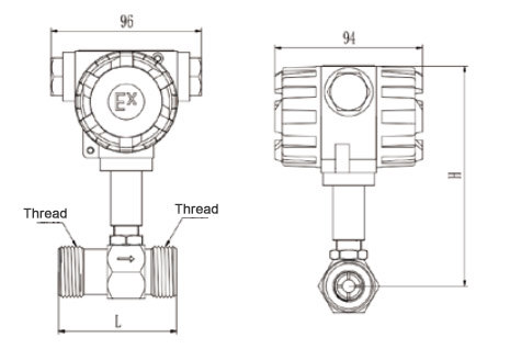
Dimensions Figure 2 (Internal Thread Connection Type)
| Meter Caliber mm |
L mm |
D mm |
K mm |
H( mm) | d mm |
n Number Of Holes |
Standard Pressure Resistance |
|||||||||||||||||
| Pulse Type | Explosion-Proof Pulse Type |
4-20mA Output Type |
Intelligent Display Type |
|||||||||||||||||||||
| 15 | 75 | 95 | 65 | 175 | 180 | 180 | 245 | 14 | 4 | 1.6 MPa |
||||||||||||||
| 20 | 85 | 105 | 75 | 185 | 190 | 190 | 255 | 14 | 4 | |||||||||||||||
| 25 | 100 | 115 | 85 | 200 | 195 | 195 | 260 | 14 | 4 | |||||||||||||||
| 32 | 120 | 140 | 100 | 210 | 215 | 215 | 275 | 18 | 4 | |||||||||||||||
| 40 | 140 | 150 | 110 | 195 | 220 | 220 | 285 | 18 | 4 | |||||||||||||||
| 50 | 150 | 165 | 125 | 230 | 235 | 235 | 295 | 18 | 4 | |||||||||||||||
| 65 | 175 | 185 | 145 | 255 | 260 | 260 | 325 | 18 | 8 | |||||||||||||||
| 80 | 200 | 200 | 160 | 260 | 265 | 265 | 330 | 18 | 8 | |||||||||||||||
| 100 | 220 | 220 | 180 | 285 | 285 | 285 | 350 | 18 | 8 | |||||||||||||||
| 125 | 250 | 250 | 210 | 310 | 315 | 315 | 380 | 18 | 8 | |||||||||||||||
| 150 | 300 | 285 | 240 | 345 | 345 | 345 | 410 | 22 | 8 | |||||||||||||||
| 200 | 360 | 340 | 295 | 395 | 400 | 400 | 465 | 22 | 12 | |||||||||||||||
Pulse Output Wiring Diagram

Basic Structure Diagram Of Converter

Installation Location
| SN51- | 025 | D | 1 | A | P1 | A | D | Detailed description | ||||||||||||||||||||||||||||
| SN51- | SN51 Series Turbine Flow Sensors | |||||||||||||||||||||||||||||||||||
| SN-51A | Model A (protection level: IP67) (explosion-proof level CT6) | |||||||||||||||||||||||||||||||||||
| SN-51B | Model B (Protection Level: IP67) (Explosion-proof Level CT6) | |||||||||||||||||||||||||||||||||||
| SN51-C | Model C (Protection level: IP65) | |||||||||||||||||||||||||||||||||||
| 025 | "Calibration option, 025 represents DN25 pipe (for special pipe diameter please consult sales engineer)" | |||||||||||||||||||||||||||||||||||
| A | Battery-powered on-site display, no output | |||||||||||||||||||||||||||||||||||
| B | Pulse signal output, no display (NPN or PNP) | |||||||||||||||||||||||||||||||||||
| C | Analog quantity 4-20mA output, no display | |||||||||||||||||||||||||||||||||||
| D | On-site display, analog quantity 4-20mA output | |||||||||||||||||||||||||||||||||||
| E | On-site display, analog quantity 2-10V output | |||||||||||||||||||||||||||||||||||
| F | On-site display, analog quantity 1-5V output | |||||||||||||||||||||||||||||||||||
| G | In-place display, pulse signal output (NPN or PNP) | |||||||||||||||||||||||||||||||||||
| 1 | RS485 Communication | |||||||||||||||||||||||||||||||||||
| 2 | HART protocol | |||||||||||||||||||||||||||||||||||
| 1 | Internal thread sealing connection (suitable for ≤DN32 diameter) | |||||||||||||||||||||||||||||||||||
| 2 | Flange connection (suitable for ≥DN15 diameter) | |||||||||||||||||||||||||||||||||||
| 3 | Sanitary grade clamp connection | |||||||||||||||||||||||||||||||||||
| 4 | Quick seal hose fittings | |||||||||||||||||||||||||||||||||||
| 5 | External thread sealed connection (suitable for ≤DN32) | |||||||||||||||||||||||||||||||||||
| C | Accuracy 1.0% | |||||||||||||||||||||||||||||||||||
| P1 | Pressure withstand: 16bar | |||||||||||||||||||||||||||||||||||
| P2 | Pressure withstand: 25bar | |||||||||||||||||||||||||||||||||||
| P3 | Pressure withstand: 40bar | |||||||||||||||||||||||||||||||||||
| P4 | Pressure withstand: 63bar | |||||||||||||||||||||||||||||||||||
| P5 | Pressure withstand: 160bar (diameter ≤DN50) | |||||||||||||||||||||||||||||||||||
| P6 | Withstand voltage: 250bar (diameter ≤DN50) | |||||||||||||||||||||||||||||||||||
| P7 | Withstand voltage: 320bar (diameter ≤DN50) | |||||||||||||||||||||||||||||||||||
| P8 | Withstand voltage: 400bar (diameter ≤DN50) | |||||||||||||||||||||||||||||||||||
| A | Code break converter (optional) | |||||||||||||||||||||||||||||||||||
| C | Smart converter (optional) | |||||||||||||||||||||||||||||||||||
| D | 24V | |||||||||||||||||||||||||||||||||||
| A | 220V | |||||||||||||||||||||||||||||||||||
| C | Battery-powered (only for selection without output) | |||||||||||||||||||||||||||||||||||
| * Please indicate the media flow direction, media type, pipe diameter and desired measurement interval value when ordering. We can help you with accurate verification when leaving the factory. * If it is a viscous medium, please indicate the viscosity, temperature, medium type, and flow range. * The selection table is for parameter selection only, and the corresponding encoding is factory-delivered by the parameters. |
||||||||||||||||||||||||||||||||||||
Shanghai Kayuan Electronic
Technology Co., Ltd.
Technology Co., Ltd.
Shanghai Kayuan Electronic Technology Co.,Ltd is an enterprise specializing in the production and R & D of industrial sensors and controllers. Its main products include switches and sensors for flow, pressure, temperature, and liquid level. Turbine Flow Sensor-SN51 Suppliers in China.
In 2008, our assembly plant was established in Shanghai China,PAKU INTELLIGENT EQUIPMENT(SHANGHAI)CO.,LTD a subsidiary of Kayuan to produce the PAKU series of products. As Turbine Flow Sensor-SN51 Factory, PAKU products are now widely used in different industries, including automation complete sets of equipment, petroleum equipment, chemical equipment, power equipment, welding equipment, steel equipment, metallurgical equipment, automobiles, and water treatment. We adopt advanced technology and manufacturing processes across the board. With our professional design and production technology, comprehensive product lines, excellent quality, and sales network services, we can not only provide users with timely and professional technical support but also offer high - quality one - stop services.
We have served many customers at home and abroad, and offer Turbine Flow Sensor-SN51 Wholesale, our products are sold to countries such as Canada, the United States, Brazil, Indonesia, Vietnam, Thailand, and Russia. We welcome extensive cooperation with OEM and ODM customers.


information
 [email protected]
![]() +86-13386111894 / +86-021-37566990
+86-13386111894 / +86-021-37566990
![]() B-4th Floor, Lane 1313, Nanting Road, Nanqiao Town, Fengxian District, Shanghai, China
B-4th Floor, Lane 1313, Nanting Road, Nanqiao Town, Fengxian District, Shanghai, China

Product Links