 en
en English
 Русский
 España
 عرب .
عرب .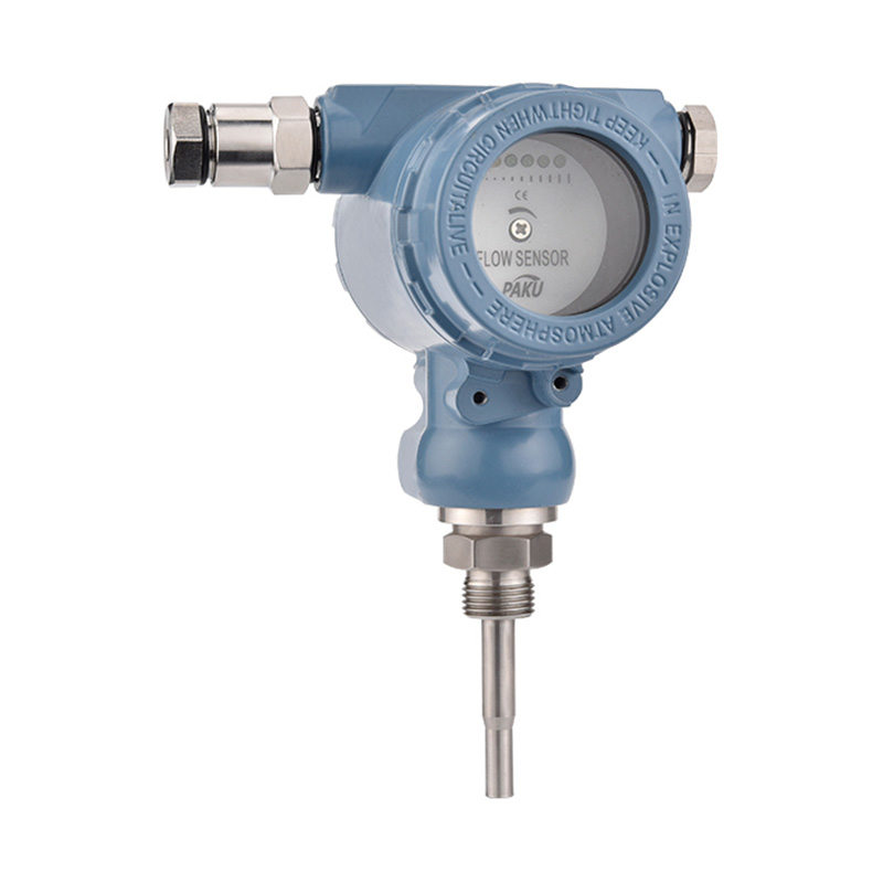


If you need any help, please feel free to contact us
inquire
If you have any further questions, please call +86-021-37566990 or fill out the inquiry form.
Get coupons PDF DownloadMetal tube float (rotor) flowmeter-SN60A
Product introduction
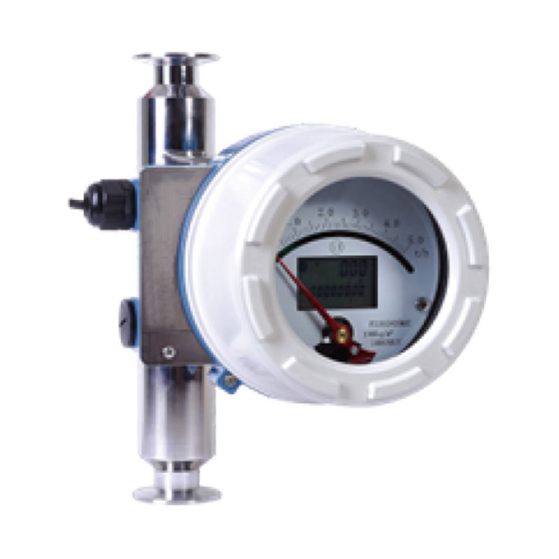
Metal tube float flowmeter (metal tube rotor flowmeter) is a commonly used in industrial automation process control of a variable area flow measurement instrument. It has a small size, large detection range, easy to use and so on, it can be used to measure the flow of liquids, gases and steam, especially suitable for low-flow rate and small flow measurement. Over the years, the metal tube float flowmeter with its excellent performance and reliability, as well as a better performance-price ratio, in the petrochemical, iron and steel, electric power, metallurgy, light industry, food, pharmaceutical, water treatment and other industries have been widely used. This manual is aimed at professional and technical personnel, applicable to the design and selection of metal tube float flowmeter, but also can be used for end-users in the use of reference. The manual introduces the working principle, functional characteristics, technical parameters, instrument type and shape, flow calculation, wiring and installation, maintenance, etc. of metal tube float flowmeter. This manual is only for the design selection and use of metal tube float flowmeter, while the manufacturer reserves the right to improve some technical parameters without prior notice. Reliable and maintenance-free
Functional Features
Measuring Principle
Measurement Schematic
Technical Parameters
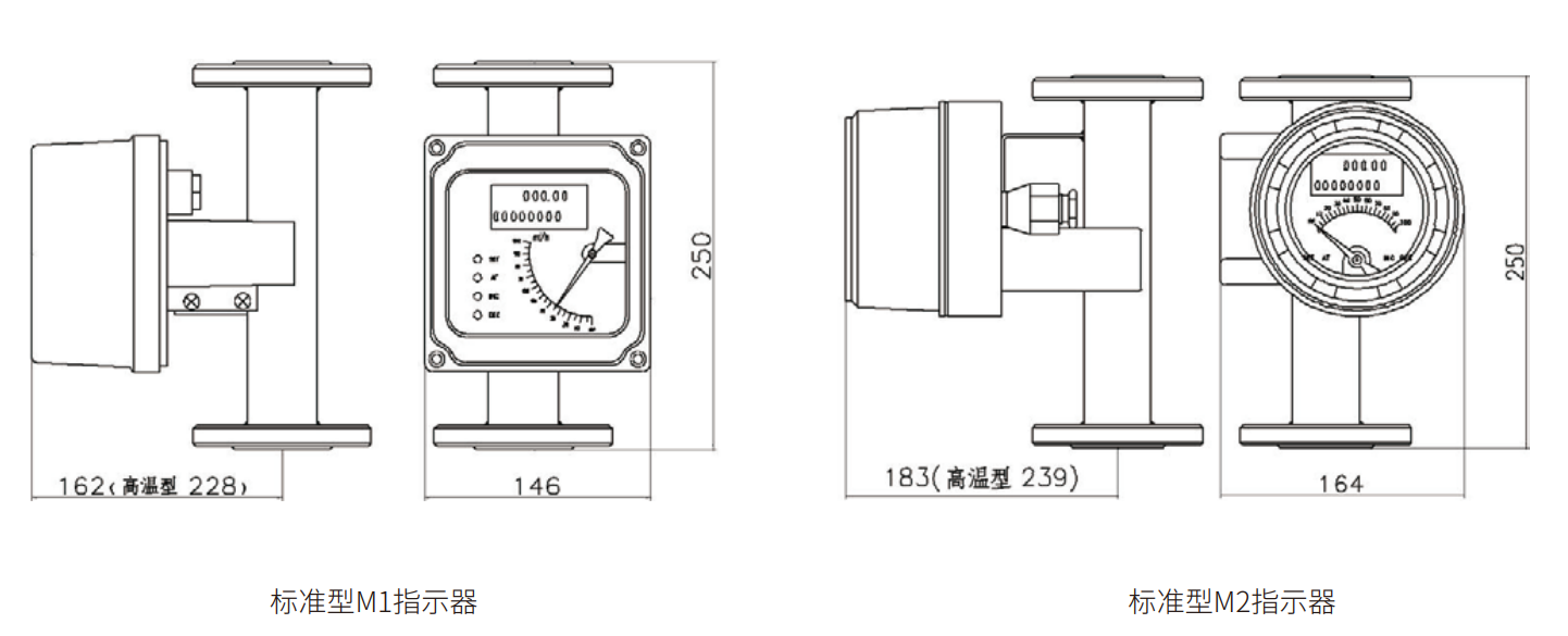
Dimension Drawing
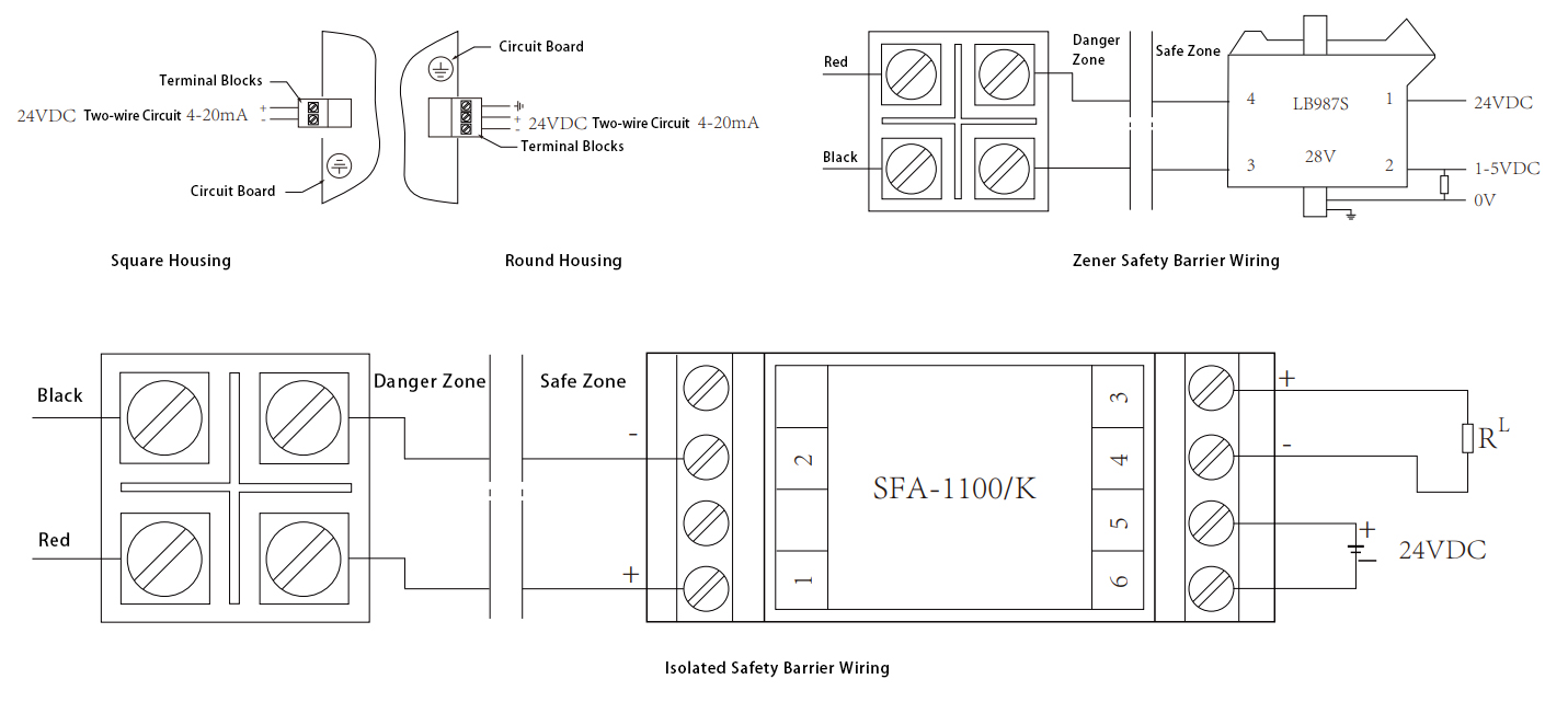
Wiring Diagram
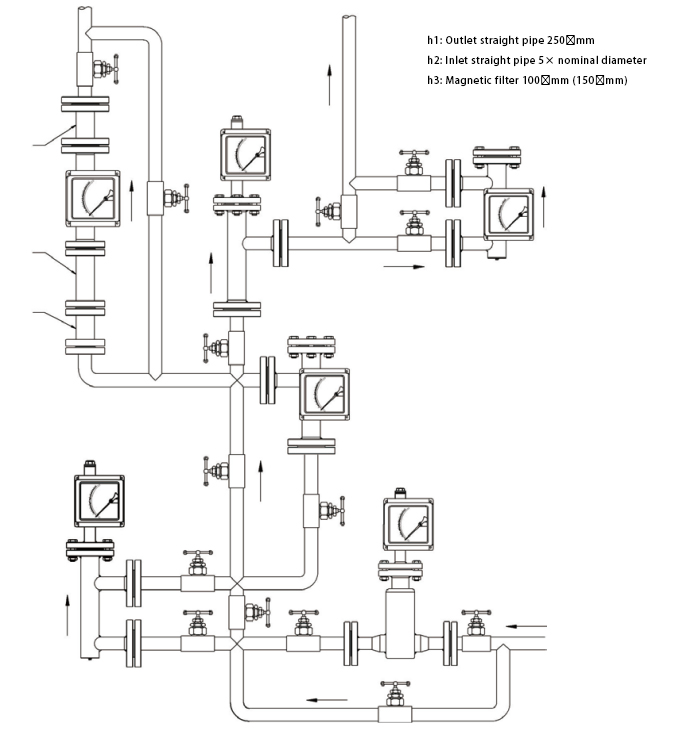
Installation
Selection Table
Suitable for small diameter and low flow rate media flow measurement
- Reliable, low maintenance and long life
-Low requirements for straight pipe sections
- Wide range ratio 10:1
-Dual line LCD with instantaneous/accumulative flow display
- Keypad on the indicator, easy to operate and set up
- All-metal construction, suitable for high temperature, high pressure and strong corrosive media.
Non-contact magnetic coupling drive
-Can be used in flammable, explosive hazardous occasions
- DC power supply or battery power supply available
With data recovery, data backup and power-down protection function.
-Multi-parameter calibration function
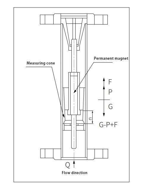
Metal tube float flowmeter mainly consists of two main components: sensor and indicator. The sensor consists of a connecting flange, a measuring cone, a float and an upper and lower guide; the indicator consists of a shell, a magnetic drive system, a dial and an electrical telemetry system. Inside the vertical conical measuring tube, there is an upward and downward movable measuring part, the float (Figure 1). When the fluid passes through the conical tube from bottom to top, the float is forced by the fluid and moves upward along the conical tube. As the fluid flow increases, the displacement of the float increases; conversely, as the fluid flow decreases, the displacement of the float decreases. In other words, the flow rate of the fluid determines the position of the float in the measuring tube and thus the size of the annular area between the float and the conical tube. When the fluid flow is maintained at a constant flow rate Q, the float is in dynamic equilibrium at position h in the conical tube, where the annular area between the float and the conical tube remains constant. The float is subjected to three forces: the gravitational force of the float G, the buoyant force of the float F, and the force of the fluid on the float P. These three forces are in equilibrium. According to the fluid dynamics of the Park's endeavour equation, the principle of force equilibrium and the law of fluid continuity, it can be calculated at this time through the annular area of the instantaneous fluid flow, so the metal tube float flowmeter is the principle of variable area measurement of flow. Figure 1 Inside the float, embedded in a high-performance permanent magnet, when the float is in the equilibrium position, the float around the formation of a uniform and stable magnetic field. On the outside of the conical tube, a magnetic sensor is installed, so that the linear displacement of the float in the measuring tube can be transmitted to the indicator through non-contact form, and after detection and processing, it is finally displayed on the indicator dial or output the corresponding standard 4-20mA current signal.
| Meter aperture | DN15, DN25, DN50, DN80, DN100, DN150 (for other calibres please consult the manufacturer) |
| Flow range | Liquid: 1.0~150,000l/h Gas: 0.05~3000m3/h (See page 11 for flow rate range.) |
| Range ratio | 10 :1 , 20 :1 (special) |
| Accuracy | Level 1.5 , Level 1.0 (special) |
| Pressure rating | DN15, DN25, DN50: 4.0MPa (max. 20MPa) DN80, DN100, DN150: 1.6MPa (max.: DN80: 10MPa; DN100: 6.4MPa; DN150: 4.0MPa) |
| Medium temperature | Standard: -30℃ ~ +120℃ , High temperature: 120℃ ~ 350℃ |
| Power supply | 24VDC (12 ~ 36VDC), 220VAC |
| Output signal | 4 ~ 20mADC (2-wire), can be attached to the HART protocol |
| Output load | 500Ω (24V power supply) |
| Ambient temperature | Local type: -40℃ ~ 120℃ Remote type: -30℃ ~ 60℃ |
| Storage conditions | Temperature: -40℃ ~ 85℃ Humidity: ≤ 85 |
| Connection method | Flange connection, flange standard: GB/T9119-2000, users can specify (other connections can be negotiated with the manufacturer) |
| Cable connection | M20 × 1.5, 1/2 NPT |
| Shell protection | IP65 |
| Explosion-proof symbol | Intrinsically safe: Ex ia IICT6, Explosion-proof: Ex d IICT6 |
| Viscosity of the medium | DN15: η < 5mPa.s DN25: η < 250mPa.s DN50~ DN150: η < 300mPa.s |
| Material of the connection | R1: 304 , 06Cr19Ni10 R0: 316 , 06Cr17Ni12Mo2 RL: 316L , 022Cr17Ni12Mo2 Ti: Titanium alloy RP: PTFE lining |
| SN60A- | A | B | C | D | E | F | G | H | elaborate on | ||||||||||||||||||||||||
| SN60A- | SN60A Series Metal Tube Float Flowmeter | ||||||||||||||||||||||||||||||||
| Measuring tube structure | 1 | Bottom Input and Output | |||||||||||||||||||||||||||||||
| 2 | Top Input and Output | ||||||||||||||||||||||||||||||||
| 3 | Bottom Input and Output | ||||||||||||||||||||||||||||||||
| 4 | Bottom Transverse Input and Output | ||||||||||||||||||||||||||||||||
| 5 | Right Input and Output | ||||||||||||||||||||||||||||||||
| 6 | Left Input and Output | ||||||||||||||||||||||||||||||||
| Catch material | R0 | Stainless Steel 316 | |||||||||||||||||||||||||||||||
| R1 | Stainless Steel 304 | ||||||||||||||||||||||||||||||||
| RP | PTFE (PTFE) | ||||||||||||||||||||||||||||||||
| Ti | Titanium Alloy | ||||||||||||||||||||||||||||||||
| RL | Stainless Steel 316L | ||||||||||||||||||||||||||||||||
| HC | Hastelloy C | ||||||||||||||||||||||||||||||||
| Pipe calibre | DN … | Calibre Selection: DN15, DN 25, DN 50, DN 80, DN 100, DN 125, DN 150, DN 200 |
|||||||||||||||||||||||||||||||
| K… | Hygiene K15, K20, K25, K32, K38, K51, K63, K76, K101 | ||||||||||||||||||||||||||||||||
| add-on structure | T | Jacketed | |||||||||||||||||||||||||||||||
| Z | Damped | ||||||||||||||||||||||||||||||||
| G | High-temperature | ||||||||||||||||||||||||||||||||
| Y | High-pressure | ||||||||||||||||||||||||||||||||
| Indicator form code combinations | M0 | In-situ indicator, mechanical pointer to indicate instantaneous flow | |||||||||||||||||||||||||||||||
| M1 | Square housing, mechanical pointer for instantaneous flow, LCD for instantaneous/cumulative flow | ||||||||||||||||||||||||||||||||
| M2 | Round housing (white), mechanical pointer for instantaneous flow, also available with LCD for instantaneous/cumulative |
||||||||||||||||||||||||||||||||
| M3 | Buccaneer housing (square), mechanical pointer for instantaneous flow, also available with LCD for instantaneous/cumulative |
||||||||||||||||||||||||||||||||
| M4 | Round housing (M40), mechanical pointer for instantaneous flow, also available with LCD for instantaneous/cumulative flow |
||||||||||||||||||||||||||||||||
| M5 | Mechanical pointer for instantaneous flow, also with LCD for instantaneous/accumulative flow |
||||||||||||||||||||||||||||||||
| M6 | Small round stainless steel housing, mechanical pointer for instantaneous flow, also with LCD for instantaneous/accumulative flow |
||||||||||||||||||||||||||||||||
| M7 | Small stamped stainless steel housing, mechanical pointer for instantaneous flow | ||||||||||||||||||||||||||||||||
| M8 | Stamped large stainless steel housing, mechanical pointer to indicate instantaneous flow, also available with instantaneous/accumulative flow display |
||||||||||||||||||||||||||||||||
| M9 | Round housing (blue), mechanical pointer for instantaneous flow, also available with instantaneous/cumulative flow on LCD flow rate, instantaneous/cumulative flow rate can also be displayed on the LCD |
||||||||||||||||||||||||||||||||
| M10 | Stamped Stainless steel housing (diameter 146 mm), mechanical pointer for instantaneous flow | ||||||||||||||||||||||||||||||||
| M11 | Round housing (M30), mechanical pointer for instantaneous flow Instantaneous/cumulative flow also available on LCD |
||||||||||||||||||||||||||||||||
| M12 | Round housing (double wiring holes), mechanical pointer for instantaneous flow Instantaneous/cumulative flow also available on LCD |
||||||||||||||||||||||||||||||||
| Power supply method | 0 | Battery operated, not available | |||||||||||||||||||||||||||||||
| A | 224VDC 2-wire power supply, 4-20mA signal output, without backlight | ||||||||||||||||||||||||||||||||
| B | 24VDC 3-wire and 4-wire power supply | ||||||||||||||||||||||||||||||||
| C | 24VDC 2-wire power supply, 4-20mA signal output, with backlight available | ||||||||||||||||||||||||||||||||
| D | 24VDC 3-wire and 4-wire power supply, 4-20mA signal output, with backlight | ||||||||||||||||||||||||||||||||
| Explosion-proof symbol | M | General non-explosion-proof | |||||||||||||||||||||||||||||||
| i | Intrinsically safe Ex ia Ⅱ CT6 | ||||||||||||||||||||||||||||||||
| d | Explosion-proof Ex d Ⅱ CT6 | ||||||||||||||||||||||||||||||||
| Alarm or pulse output | KO | No alarm or pulse output | |||||||||||||||||||||||||||||||
| K1 | Lower-limit alarm or one pulse output | ||||||||||||||||||||||||||||||||
| K2 | Upper-limit and lower-limit alarms or double pulses | ||||||||||||||||||||||||||||||||
| K3 | Upper-limit and lower-limit alarms or double pulse outputs | ||||||||||||||||||||||||||||||||
| * The selection table is for parameter selection only and is shipped with the corresponding code for the parameter. | |||||||||||||||||||||||||||||||||
Shanghai Kayuan Electronic
Technology Co., Ltd.
Technology Co., Ltd.
Shanghai Kayuan Electronic Technology Co.,Ltd is an enterprise specializing in the production and R & D of industrial sensors and controllers. Its main products include switches and sensors for flow, pressure, temperature, and liquid level. Metal tube float (rotor) flowmeter-SN60A Suppliers in China.
In 2008, our assembly plant was established in Shanghai China,PAKU INTELLIGENT EQUIPMENT(SHANGHAI)CO.,LTD a subsidiary of Kayuan to produce the PAKU series of products. As Metal tube float (rotor) flowmeter-SN60A Factory, PAKU products are now widely used in different industries, including automation complete sets of equipment, petroleum equipment, chemical equipment, power equipment, welding equipment, steel equipment, metallurgical equipment, automobiles, and water treatment. We adopt advanced technology and manufacturing processes across the board. With our professional design and production technology, comprehensive product lines, excellent quality, and sales network services, we can not only provide users with timely and professional technical support but also offer high - quality one - stop services.
We have served many customers at home and abroad, and offer Metal tube float (rotor) flowmeter-SN60A Wholesale, our products are sold to countries such as Canada, the United States, Brazil, Indonesia, Vietnam, Thailand, and Russia. We welcome extensive cooperation with OEM and ODM customers.


information
 [email protected]
![]() +86-13386111894 / +86-021-37566990
+86-13386111894 / +86-021-37566990
![]() B-4th Floor, Lane 1313, Nanting Road, Nanqiao Town, Fengxian District, Shanghai, China
B-4th Floor, Lane 1313, Nanting Road, Nanqiao Town, Fengxian District, Shanghai, China

Product Links