 en
en English
 Русский
 España
 عرب .
عرب .

If you need any help, please feel free to contact us
inquire
What are the four types of Flow Sensors?
Flow sensors measure the rate at which a liquid or gas moves through a pipe, channel, or open conduit — one of the most fundamental measurements in industrial process control, HVAC, water management, medical devices, and energy metering. While dozens of specific technologies exist, virtually all flow sensors fall into one of four primary measurement categories: differential pressure-based, velocity-based, positive displacement, and mass flow. Each category uses a fundamentally different physical principle to detect flow, which determines the fluids it handles well, the accuracy it achieves, the installation requirements it imposes, and the conditions under which it fails.
Choosing the wrong type of flow sensor for an application is one of the most costly instrumentation mistakes in process engineering — not because sensors are cheap (industrial flow meters can cost from £50 to over £50,000), but because incorrect selection leads to poor measurement accuracy, premature sensor failure, process control errors, and safety incidents. Understanding what distinguishes these four types — and which applications each is suited to — is the starting point for any flow measurement specification.
Type 1: Differential Pressure Flow Sensors
Differential pressure (DP) flow sensors are the oldest and most widely deployed category of flow measurement technology. They operate on Bernoulli's principle: when a fluid flows through a restriction in a pipe, its velocity increases and its static pressure drops. By measuring the pressure difference (differential pressure) between the upstream and downstream sides of the restriction, the volumetric flow rate can be calculated. The relationship between flow rate and differential pressure follows the square root law — doubling the flow rate produces four times the differential pressure — which is important for understanding the technology's turndown limitations.
Common DP Flow Sensor Technologies
- Orifice plate: A flat plate with a precisely machined hole inserted perpendicular to the flow path. The simplest and least expensive DP element. Widely used in oil and gas, chemical processing, and steam measurement. Typical accuracy of ±0.5–2% of full scale. Causes a permanent pressure loss — a significant energy cost at high flow rates.
- Venturi tube: A gradually converging and diverging tube section that creates a pressure differential with significantly lower permanent pressure loss than an orifice plate (typically 10–25% of the differential produced vs 50–80% for orifice plates). Used where energy efficiency is important: large water mains, hydrocarbon pipelines.
- Flow nozzle: A performance intermediate between orifice plate and venturi — higher beta ratio range, lower pressure loss than orifice, used for steam and high-velocity gas applications.
- Pitot tube / averaging pitot (annubar): Measures the impact pressure of the flowing fluid at one or more points across the pipe cross-section. Low cost, suitable for large pipe diameters (DN200–DN3000), and can be inserted through a hot tap without shutting down the process. Used in HVAC air flow, large water mains, and flare gas measurement.
- Variable area meter (rotameter): A float rises in a vertically mounted tapered tube as flow increases, achieving equilibrium where the upward drag force balances gravity. A simple, low-cost device with no moving electronics — widely used for low-flow laboratory and process applications. Typical accuracy ±2–5%.
Strengths and Limitations of DP Flow Sensors
DP flow sensors are robust, well-understood, and suitable for a very wide range of fluids and temperatures. They can handle steam, gas, slurries, and high-pressure liquids. The principal limitation is turndown ratio — typically 3:1 to 5:1 for orifice plates, compared to 10:1 to 100:1 for velocity or mass flow technologies. This means DP sensors lose accuracy rapidly at low flow rates (below 30–40% of maximum range), making them unsuitable for applications with widely variable flow. The square root relationship also means that errors at low differential pressure readings translate to disproportionately large flow errors.
Best Applications for DP Flow Sensors
Oil and gas pipeline metering, steam flow in power generation, chemical process lines, HVAC air flow measurement in large ducts, and custody transfer of hydrocarbons (orifice plates to ISO 5167 standards) are the dominant applications. DP flow is specified in roughly 20–25% of all new industrial flow meter installations globally, making it the second most deployed technology category after electromagnetic flow sensors in liquid service.
Type 2: Velocity Flow Sensors
Velocity flow sensors measure the speed of the fluid at one or more points in the flow cross-section and derive volumetric flow rate by multiplying velocity by the known pipe cross-sectional area. Unlike DP sensors, which infer velocity from a pressure difference, velocity sensors directly measure how fast the fluid is moving — either by detecting the transit time of a signal through the fluid, measuring the frequency of vortices shed by a bluff body, or using the interaction between a magnetic field and a conductive fluid.
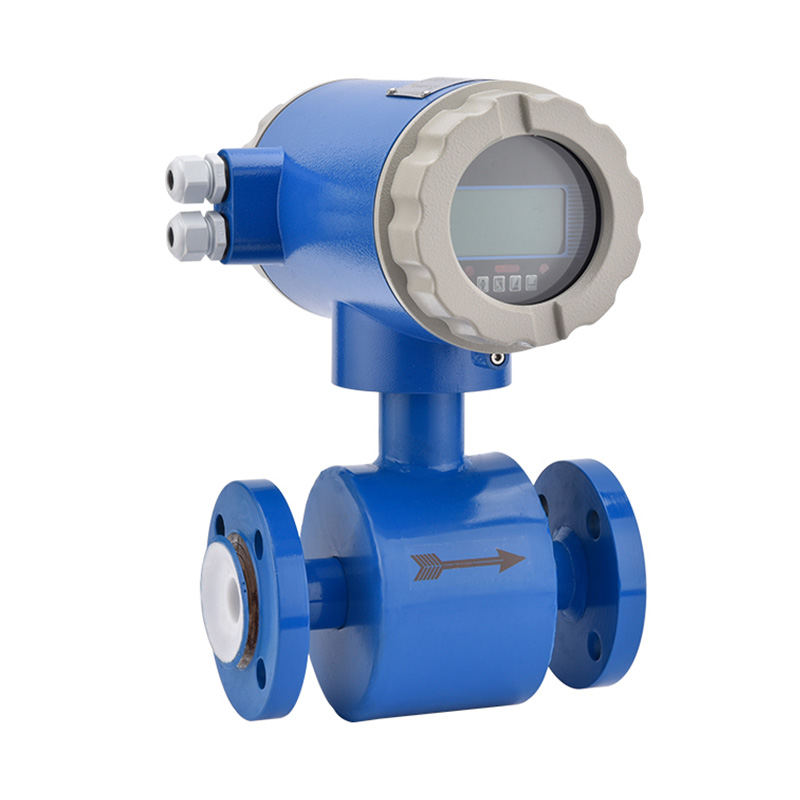
Electromagnetic (Mag) Flow Sensors
Electromagnetic flow sensors apply Faraday's law of electromagnetic induction: a conductive liquid flowing through a magnetic field generates a voltage proportional to its velocity. Electrodes mounted in the pipe wall detect this voltage. Mag meters are the most widely sold category of industrial flow sensor globally, with strengths including no moving parts, no obstruction to flow (zero pressure loss), suitability for slurries and dirty liquids, bidirectional measurement, and excellent accuracy (±0.2–0.5% of reading) over turndown ratios of 30:1 or better. Critical limitation: the fluid must be electrically conductive — a minimum conductivity of typically 5 µS/cm is required, which excludes hydrocarbons, most gases, and ultrapure water.
Ultrasonic Flow Sensors
Ultrasonic sensors measure the transit time difference of sound pulses sent diagonally upstream and downstream through the fluid — a faster upstream-to-downstream transit time indicates higher flow velocity. Clamp-on ultrasonic sensors apply transducers to the outside of the pipe without any penetration, enabling flow measurement on existing pipes without shutdown and making them ideal for retrofit applications. Inline ultrasonic meters with multiple acoustic paths achieve custody transfer accuracy of ±0.1–0.2% of reading, making them the technology of choice for high-value natural gas and refined petroleum product metering. They are equally suitable for clean liquids and gases, and have no pressure drop. Limitation: clamp-on models are sensitive to pipe material, wall thickness, and fluid homogeneity; heavy slurries and two-phase flows (gas-liquid mixtures) attenuate the acoustic signal and reduce accuracy.
Vortex Flow Sensors
Vortex sensors place a bluff body (a shedder bar) in the flow path. As fluid passes the bluff body, it alternately sheds vortices from each side — a phenomenon called the Kármán vortex street. The frequency of vortex shedding is directly proportional to velocity. The K-factor (vortices per unit volume) remains constant over a very wide Reynolds number range, giving vortex meters excellent rangeability (20:1 to 40:1) and making them insensitive to fluid density, viscosity, and composition changes — a significant advantage over DP sensors. Vortex meters are widely used for steam, compressed air, and general process gas and liquid measurement. They are unsuitable for very low velocity flows (below the minimum Reynolds number needed for stable vortex shedding) and for fluids with high viscosity.
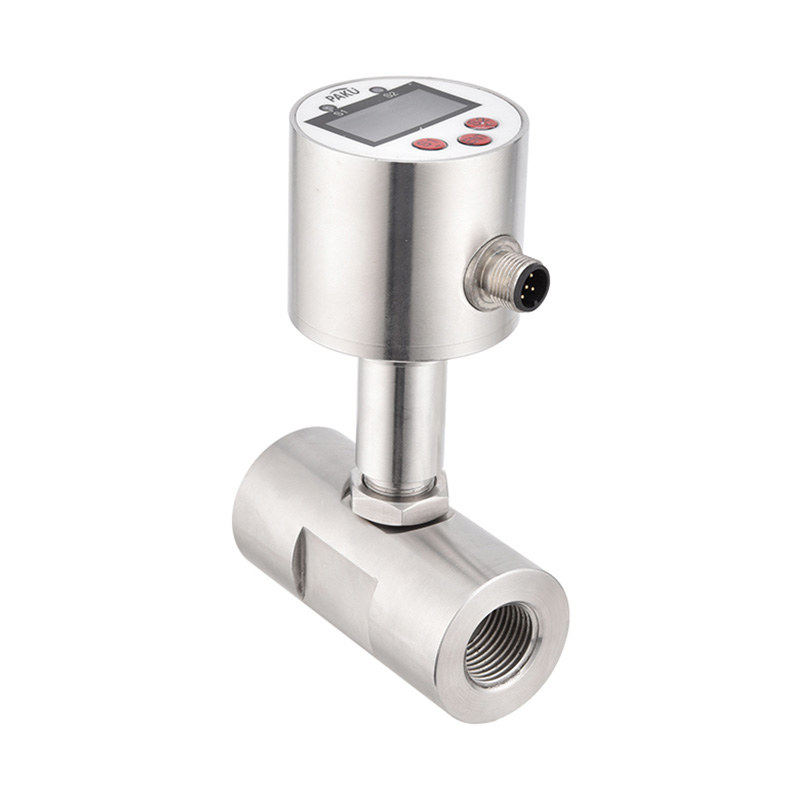
Turbine Flow Sensors
A multi-bladed rotor spins freely in the fluid flow, its rotational speed proportional to velocity. A magnetic or optical pickup detects blade passing frequency. Turbine meters offer high accuracy (±0.1–0.5% of reading) and high turndown ratios (10:1 to 25:1), making them suitable for custody transfer of clean liquids and gases — fuel metering at airfields, natural gas billing metering, and pharmaceutical process measurement are typical applications. They are sensitive to flow profile distortions (requiring upstream straight pipe runs of 10–20 diameters), cannot handle dirty or abrasive fluids without bearing wear, and are unidirectional.
Best Applications for Velocity Flow Sensors
Velocity sensors dominate water and wastewater treatment (electromagnetic), natural gas transmission (ultrasonic), steam distribution (vortex), and petroleum product transfer (turbine). Their combination of wide rangeability, good accuracy, and (for electromagnetic and ultrasonic types) absence of moving parts makes them the preferred choice for the majority of new industrial flow meter installations.
Type 3: Positive Displacement Flow Sensors
Positive displacement (PD) flow sensors operate on a fundamentally different principle from DP and velocity technologies. Rather than inferring flow from a physical effect, PD meters directly divide the fluid into discrete, known volumes and count the number of volumes that pass through the meter per unit time. The result is a direct, mechanically counted volumetric measurement with accuracy and repeatability that is independent of fluid velocity profile, viscosity, or upstream pipe conditions — characteristics that make PD meters uniquely suitable for certain demanding applications.
How Positive Displacement Meters Work
The fluid fills a precision-machined measuring chamber, is physically displaced by a rotating or reciprocating mechanism (gears, pistons, lobes, or diaphragm), and exits. Each complete cycle of the mechanism displaces a precisely known volume. A counter tallies the cycles, giving a highly accurate cumulative volume total. PD meters typically achieve accuracy of ±0.1–0.5% of reading with repeatability of ±0.05% — the best repeatability of any flow technology, which is why they dominate applications where precise billing and custody transfer of expensive fluids are required.
Common PD Flow Sensor Technologies
- Oval gear meters: Two oval-shaped gears mesh and rotate, trapping fixed volumes of fluid in the cavities between the gears and the meter housing. Widely used for oil metering, chemical dosing, fuel dispensing, and hydraulic fluid measurement. Handle viscous fluids very well — accuracy actually improves with increasing viscosity as leakage past the gears decreases.
- Rotary lobe (roots) meters: Two figure-eight shaped rotors counter-rotate, sweeping precise volumes of gas through the meter. The standard technology for domestic and commercial gas billing meters in many countries. Very accurate (±1–2%) at low flow rates — the regime where most domestic gas consumption occurs.
- Piston meters: A reciprocating or oscillating piston displaces fixed volumes of liquid per stroke. Used for very precise low-flow measurement of viscous liquids, fuels, and chemicals — typical flows from 0.01 to 10 L/min.
- Diaphragm meters: Two flexible diaphragm chambers alternately fill and empty, driving a mechanical counter. The universal technology for residential natural gas meters worldwide — over 150 million diaphragm gas meters are in service globally, and their simple mechanical design gives operational lifetimes exceeding 20 years.
- Nutating disc meters: A disc precesses (nutates) in a spherical chamber, dividing fluid into fixed volumes per nutation cycle. The standard technology in residential and small commercial water meters in North America.
Limitations of Positive Displacement Sensors
PD meters have moving mechanical parts that are in direct contact with the process fluid — a fundamental limitation in several dimensions. Abrasive particles or hard contamination in the fluid cause rapid bearing and gear wear. High-viscosity fluids at high flow rates impose significant pressure drops across the meter. Maximum operating pressure and temperature are constrained by the sealing and material options for the moving components. PD meters are generally unsuitable for gases at low pressure (insufficient energy to overcome the meter's mechanical resistance), for high-flow applications (pressure drop becomes unacceptable), and for fluids containing particulate matter above approximately 50–100 microns without upstream filtration.
Type 4: Mass Flow Sensors
Mass flow sensors measure mass flow rate directly — the mass of fluid passing a point per unit time (kg/s, kg/h, or lb/min) — rather than volumetric flow rate. This distinction is critically important in many process and commercial applications. For most chemical reactions, combustion processes, and custody transfer of gases, mass is the physically meaningful quantity — not volume. The volume of a gas changes dramatically with pressure and temperature, but its mass does not. A flow sensor that measures mass directly eliminates the need for separate pressure and temperature compensation — which introduces additional measurement uncertainty and instrument cost.
Coriolis Mass Flow Sensors
Coriolis meters vibrate one or two curved or straight tubes at their natural resonant frequency. When fluid flows through the vibrating tube, the Coriolis force induced by the combination of vibration and flow causes a measurable phase shift (twist) in the tube oscillation. The magnitude of the phase shift is directly and linearly proportional to mass flow rate, independent of fluid density, viscosity, pressure, or temperature. This gives Coriolis meters the highest accuracy of any flow technology: typically ±0.1–0.2% of reading for liquids and ±0.35–0.5% for gases, with rangeability of 100:1 or better. Coriolis meters simultaneously measure fluid density (from the oscillation frequency) and can calculate volumetric flow, net oil content, and concentration — making them a multi-variable sensor. They are used for custody transfer of high-value liquids (LNG, petrochemicals, food ingredients), pharmaceutical batching, and chemical blending where mass accuracy is non-negotiable. Primary limitations are high cost (£3,000–£50,000+ for industrial models), sensitivity to external vibration, and pressure drop at high flow rates in small tube sizes.
Thermal Mass Flow Sensors
Thermal mass flow sensors measure the heat carried away from a heated element by the flowing gas — the greater the mass flow, the more heat is transferred. Two main designs exist: constant temperature (CT) sensors that maintain a fixed temperature differential between a heated probe and the flow, measuring the power required; and constant power (CP) sensors that apply fixed heating power and measure the resulting temperature differential. Thermal mass flow sensors are the dominant technology for low-to-medium flow gas measurement, particularly for clean, dry gases including compressed air, nitrogen, natural gas, hydrogen, and specialty process gases. They are compact, require no moving parts, have no pressure drop (insertion designs), and deliver accuracy of ±1–3% of full scale with rangeability up to 100:1. They are not suitable for liquids and require recalibration if the gas composition changes significantly.
Best Applications for Mass Flow Sensors
Coriolis meters are specified for high-accuracy custody transfer of liquids and dense gases (LNG, CO₂), pharmaceutical batch manufacturing, chemical reactor feed control, and food/beverage ingredient dosing. Thermal mass sensors are standard for compressed air and industrial gas sub-metering, burner air-to-fuel ratio control, semiconductor process gas control, and leak detection systems. The mass flow sensor market has grown faster than any other flow technology category over the past decade, driven by the expansion of natural gas infrastructure, pharmaceutical manufacturing, and semiconductor fabrication — all industries where mass measurement accuracy is essential.
Comparing the Four Flow Sensor Types Side by Side
Understanding the practical trade-offs between the four types requires looking at the key selection criteria together in a single comparison.
| Criterion | Differential Pressure | Velocity | Positive Displacement | Mass Flow |
|---|---|---|---|---|
| Measurement output | Volumetric (inferred) | Volumetric (direct) | Volumetric (direct) | Mass (direct) |
| Typical accuracy | ±0.5–2% | ±0.1–0.5% | ±0.1–0.5% | ±0.1–0.5% |
| Turndown ratio | 3:1 – 5:1 | 10:1 – 100:1 | 10:1 – 25:1 | 50:1 – 200:1 |
| Moving parts | Some (rotameter, none for DP sensor) | Some (turbine, none for mag/ultrasonic) | Always yes | None (Coriolis tube vibration) |
| Suitable for dirty / slurry fluids | With care (can block) | Yes (mag meter) | No (causes wear) | Yes (Coriolis) |
| Suitable for gases | Yes | Yes (vortex, ultrasonic, turbine) | Yes (lobe, diaphragm) | Yes (thermal, Coriolis) |
| Pressure drop | Moderate to high | Low to none | Moderate | Low to high (size-dependent) |
| Relative cost | Low to medium | Low to high | Medium | High (Coriolis), low–medium (thermal) |
How to Select the Right Flow Sensor Type for a Given Application
No single flow sensor type is universally superior — the correct choice depends on a structured evaluation of the fluid properties, process conditions, accuracy requirements, and practical constraints of the specific installation. A systematic selection process reduces the risk of costly misspecification.
Fluid Properties Drive Initial Technology Selection
The nature of the fluid being measured eliminates many options immediately:
- Non-conductive liquids (hydrocarbons, oils, solvents): Electromagnetic sensors are excluded. Coriolis, PD (oval gear), turbine, or ultrasonic are the primary choices.
- Slurries and dirty liquids with particles: PD meters and turbine meters are excluded. Electromagnetic (mag) sensors are the standard choice; Coriolis sensors handle moderate slurry concentrations.
- Clean dry gases: Thermal mass, vortex, turbine, ultrasonic, and DP (orifice/venturi) are all viable. Choice depends on accuracy and rangeability requirements.
- Very high viscosity fluids: PD (oval gear) sensors perform better as viscosity increases, while velocity sensors (turbine, vortex) degrade. Coriolis is viscosity-independent.
- Steam: Vortex and DP (orifice, averaging pitot) are the most common choices. Coriolis sensors handle steam but at significantly higher cost.
Accuracy and Rangeability Requirements Narrow the Choice Further
If measurement uncertainty must be within ±0.2% of reading for custody transfer or fiscal metering, only Coriolis, ultrasonic (multi-path), and high-quality turbine or PD meters qualify. If ±1–2% accuracy at a stable flow rate is acceptable (process monitoring, building energy sub-metering), DP sensors, vortex, and thermal mass sensors offer a more economical solution. Applications with highly variable flow — batch processes, peak demand loads, or systems with both minimum and maximum flow rates spanning more than 10:1 — should favour mass flow or velocity sensors with wide rangeability over DP sensors, which lose disproportionate accuracy at low flows.
Installation Constraints and Total Cost of Ownership
Practical installation factors frequently override the theoretically optimal technology choice. A large existing pipe where shutdown for inline meter installation is not feasible points to clamp-on ultrasonic or insertion-type sensors. A remote location with no power supply favours mechanical PD or DP meters. An application in a hazardous ATEX zone requires ATEX-certified instruments, which are available across all technology types but at different cost premiums. Maintenance access constraints may rule out meters requiring flow interruption for inspection. Total cost of ownership — capital cost plus installation, calibration, maintenance, and energy (pressure drop) over the expected meter life of 10–20 years — often favours the higher-capital, lower-maintenance option of a Coriolis or electromagnetic sensor over a lower-capital but higher-maintenance turbine or PD meter in continuous high-usage applications.
Emerging and Specialised Flow Sensor Technologies Beyond the Four Main Types
While the four categories above cover the overwhelming majority of industrial flow measurement applications, several additional technologies address specialised requirements that fall outside these frameworks.
- Open channel flow measurement: Weirs, flumes, and ultrasonic level sensors measure flow in rivers, sewers, irrigation channels, and drainage infrastructure where flow is not contained in a closed pipe. Governed by the Manning equation or rated flow curves for standardised weir geometries — a distinct methodology from all four closed-pipe types.
- Laser Doppler Anemometry (LDA) and Particle Image Velocimetry (PIV): Laboratory and research techniques that map full velocity profiles in a flow cross-section using laser optics. Used for fluid dynamics research, not industrial process control.
- Microfluidic MEMS flow sensors: Silicon-microfabricated thermal or pressure sensors capable of measuring extremely low gas or liquid flows — from nanolitres to microlitres per minute. Used in medical devices, analytical instruments, and semiconductor gas delivery systems where the flow rates are far below the range of any conventional industrial sensor.
- Cross-correlation flow sensors: Measure the time for a naturally occurring disturbance pattern (turbulence, concentration variation) to travel between two sensing points. Used for multiphase flow in oil and gas wells and for slurry pipelines where conventional sensors cannot achieve reliable measurement.
These specialised technologies do not displace the four main categories for standard applications — but they fill measurement gaps in extreme conditions that differential pressure, velocity, positive displacement, and mass flow sensors cannot address reliably.
information
 [email protected]
![]() +86-13386111894 / +86-021-37566990
+86-13386111894 / +86-021-37566990
![]() B-4th Floor, Lane 1313, Nanting Road, Nanqiao Town, Fengxian District, Shanghai, China
B-4th Floor, Lane 1313, Nanting Road, Nanqiao Town, Fengxian District, Shanghai, China

Product Links