 en
en English
 Русский
 España
 عرب .
عرب .

If you need any help, please feel free to contact us
inquire
Capacitive Fuel Level Sensors & Liquid Level Controls Guide
Capacitive Fuel Level Sensors: The Most Accurate Choice for Liquid Level Control
Among the available technologies for liquid level controls, capacitive fuel level sensors consistently deliver the best combination of accuracy, reliability, and compatibility with non-conductive fluids like diesel, gasoline, and hydraulic oil. They contain no moving parts, are immune to mechanical wear, and can achieve measurement accuracy of ±0.5% to ±1% of full scale in well-calibrated installations. Whether you are managing a single fuel tank or designing a multi-tank liquid level control system for industrial or fleet applications, understanding how capacitive sensors work — and where they outperform alternatives — is the fastest path to selecting the right technology.
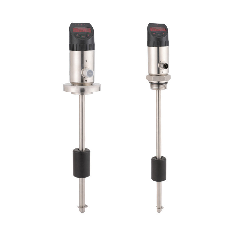
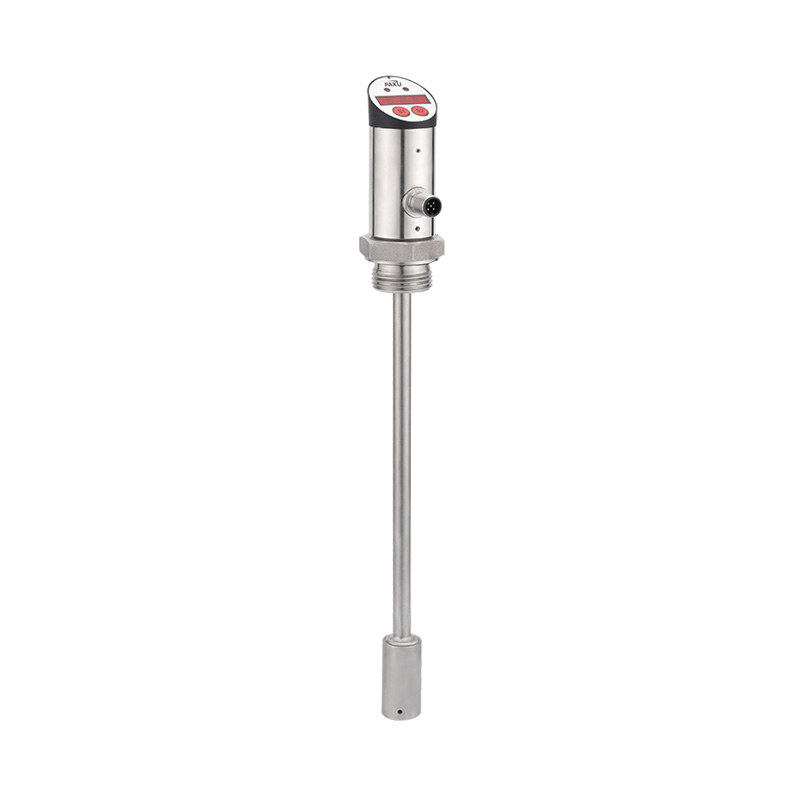
How a Capacitive Fuel Level Sensor Works
A capacitive fuel level sensor operates on the principle that the capacitance between two conductive electrodes changes when the dielectric material between them changes. In a fuel tank application, the sensor probe forms one electrode; the tank wall (or an internal reference electrode) forms the other. As the fuel level rises, the proportion of the electrode gap filled by fuel — which has a higher dielectric constant than air — increases, raising the overall capacitance of the system.
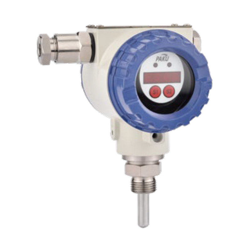
The sensor's electronics measure this capacitance change continuously and convert it to a linear analog output — typically 4–20 mA or 0–5 V DC — that represents the fuel level as a percentage of tank capacity. Because the measurement depends on dielectric properties rather than mechanical position, there are no floats, levers, or moving components to jam, corrode, or fatigue.
Key physical parameters that affect capacitive measurement performance:
- Dielectric constant (εr) of the fluid — diesel typically has εr ≈ 2.0–2.2; gasoline εr ≈ 1.9–2.1; water εr ≈ 80. The large difference between fuel and water is what makes capacitive sensors sensitive to water contamination in fuel tanks
- Electrode geometry — coaxial cylindrical probes provide more stable and interference-resistant readings than flat-plate designs in most tank installations
- Temperature variation — dielectric constants shift with temperature, so higher-quality sensors incorporate temperature compensation circuits to maintain accuracy across operating ranges of -40°C to +85°C
- Foam and aeration — entrained air bubbles lower the effective dielectric constant, causing temporary underreading during rapid filling; this is a known limitation that the system designer should account for in dynamic applications
Capacitive vs. Other Liquid Level Control Technologies
Capacitive sensors are not the right choice for every liquid level control application. Understanding how they compare to alternatives helps ensure the right technology is selected for the specific fluid, tank geometry, and environmental conditions involved.
| Technology | Measurement Type | Moving Parts | Best For | Limitations | Typical Accuracy |
|---|---|---|---|---|---|
| Capacitive | Continuous | None | Fuel, oils, non-conductive liquids | Sensitive to dielectric variation | ±0.5–1% |
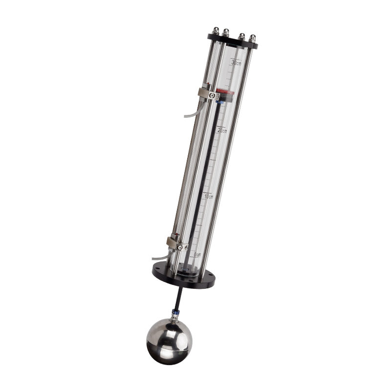
| Float (resistive) | Continuous | Yes | Simple water / fuel tanks | Mechanical wear, foam interference | ±3–5% |
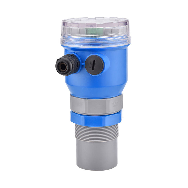
| Ultrasonic | Continuous | None | Open tanks, corrosive liquids | Foam, vapor interference; higher cost | ±1–2% |
| Pressure (hydrostatic) | Continuous | None | Deep tanks, water, process liquids | Fluid density must be stable | ±0.5–1% |
| Conductive (point) | Point detection | None | Conductive liquids (water, acids) | Non-conductive fluids only — does not work | On/off only |
The key takeaway from this comparison: capacitive fuel level sensors are the strongest choice when continuous, accurate measurement of non-conductive liquids is required without mechanical components. Ultrasonic and hydrostatic sensors are competitive alternatives for certain tank geometries, but neither handles fuel as cleanly as a capacitive probe installed inside the tank.
Applications Where Capacitive Fuel Level Sensors Are the Standard Choice
Capacitive liquid level controls have become the dominant technology in a range of demanding industries precisely because fuel and hydrocarbon measurement requirements exceed what simpler technologies can deliver reliably.
Aviation Fuel Systems
Commercial aircraft have used capacitive fuel quantity measurement systems (FQMS) as the primary fuel gauging technology since the 1970s. Airbus A320 and Boeing 737 families both use multi-probe capacitive systems with individual probes installed at multiple positions within each wing tank. The system compensates for aircraft pitch and roll attitude to calculate true volumetric fuel quantity continuously. Accuracy requirements for aviation FQMS are defined under FAA AC 25.1337-1 and EASA CS-25, demanding total system errors below ±3% of full tank capacity including all probe, densitometer, and electronics tolerances.
Commercial Vehicle and Fleet Fuel Management
Trucks, buses, and off-highway equipment increasingly use capacitive fuel level sensors in place of traditional float-arm senders to support telematics and fuel theft detection systems. A capacitive probe integrated with a CAN-bus fuel monitoring module can detect fuel level changes of as little as 1–2 liters in a 400-liter tank, making unauthorized siphoning events visible in near-real time. Fleet operators report fuel loss reductions of 15–25% after deploying capacitive sensor-based fuel management systems, primarily through deterrence and early detection of anomalies.
Standby Generator Fuel Tanks
Data centers, hospitals, and critical infrastructure facilities rely on standby generators that must be fueled and ready at all times. Capacitive level controls in these base-mounted or day tanks provide continuous level data to building management systems (BMS) and trigger automatic fuel delivery orders before reserve thresholds are breached. The no-moving-parts design is critical here: a float sender that jams or gives a false reading in a standby generator tank can mean a facility runs out of fuel during a grid outage — an unacceptable failure mode.
Industrial Process Liquid Level Controls
Beyond fuel, capacitive technology is widely used in industrial liquid level control for hydraulic fluid reservoirs, lubricant sumps, chemical dosing tanks, and coolant systems. In these applications the sensor often serves a dual function: continuous level monitoring plus water-in-oil detection, since the large dielectric constant difference between water (εr ≈ 80) and petroleum-based fluids (εr ≈ 2) makes a capacitive probe sensitive to even small water contamination levels that would be invisible to pressure or ultrasonic sensors.
Selecting the Right Capacitive Fuel Level Sensor: Key Specification Parameters
Capacitive level sensors vary significantly in construction, output type, and installation requirements. Matching the specification to the application prevents the most common failure modes.
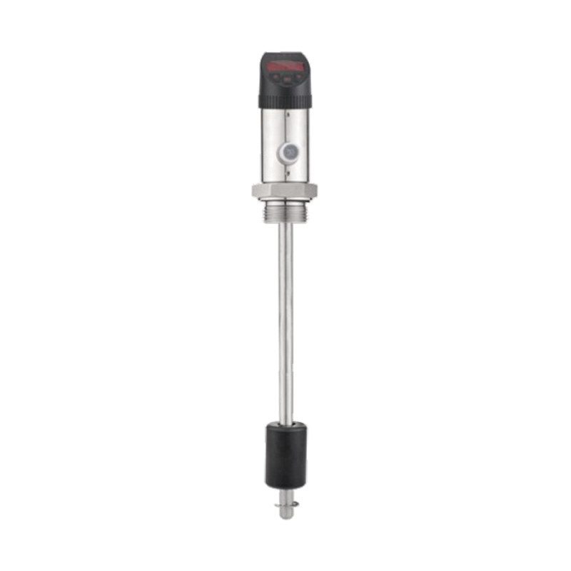
Probe Length and Tank Geometry
The probe must span the full measurement range of the tank. Most manufacturers offer custom probe lengths from 100 mm to over 3,000 mm, with the active sensing length matched precisely to the usable tank depth between empty and full reference points. In irregular tanks (saddle tanks, D-shaped cross-sections), a calibration table or linearization function in the signal conditioner maps the non-linear capacitance-to-volume relationship to an accurate volume output.
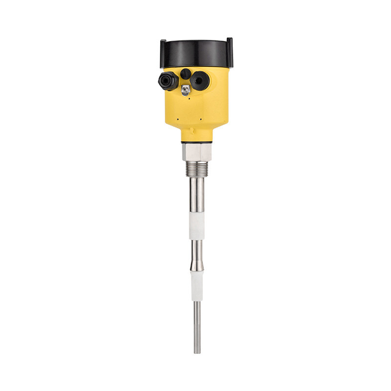
Material Compatibility
Probe construction must be chemically compatible with the stored fluid. For standard diesel and gasoline, 316L stainless steel or PTFE-coated probes are the industry standard. For aggressive chemicals, Hastelloy C-276, PVDF, or ceramic-coated electrodes are available. The insulating sleeve material between electrodes — typically PTFE, PEEK, or ceramic — is equally important, as degradation of the insulator creates leakage currents that shift calibration over time.
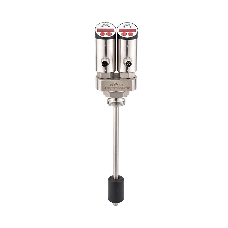
Output Signal and Interface
The output standard must match the receiving system — PLC, BMS, engine controller, or fuel management system. Common options include:
- 4–20 mA current loop — the most common industrial standard; noise-immune over long cable runs, intrinsically safe variants available
- 0–5 V or 0–10 V DC — used in automotive and mobile equipment applications where short cable runs are standard
- CANbus / J1939 — digital protocol used in heavy vehicles and off-highway equipment for direct integration with telematics and engine management systems
- Modbus RTU / RS-485 — widely used in industrial SCADA and BMS environments for multi-drop sensor networks
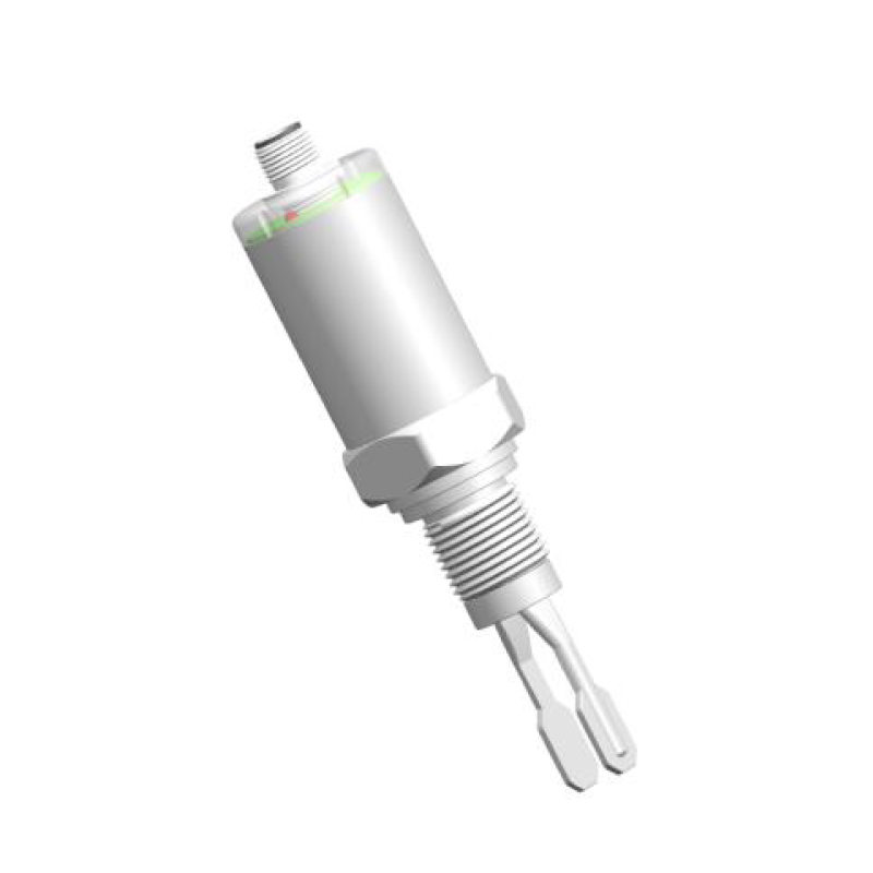
- Relay or transistor switch output — for simple high/low liquid level control alarm functions without continuous monitoring requirements
ATEX / IECEx Certification for Hazardous Areas
Any capacitive fuel level sensor installed inside a fuel tank or in a zone classified as potentially explosive must carry appropriate hazardous area certification. ATEX Zone 0 (inside fuel tank) certification requires intrinsically safe (Ex ia) circuitry, meaning the sensor electronics are designed so that even a fault condition cannot generate sufficient energy to ignite fuel vapor. This is non-negotiable in aviation, marine, and industrial above-ground fuel storage applications. Verify that the sensor's certification matches the zone classification of the installation before purchase.
Installation Best Practices for Accurate Liquid Level Measurement
Even a high-quality capacitive sensor will underperform if installed incorrectly. These practices consistently produce the best results:
- Mount the probe vertically. Capacitive probes are calibrated assuming vertical installation. Angles beyond ±5° from vertical introduce level-dependent errors as the liquid contact area on the probe changes non-linearly with tilt.
- Keep the probe away from tank inlets and agitators. Install the probe at least 200–300 mm from any inlet pipe, return line, or mechanical agitator. Turbulence and aeration at the measurement point cause erratic readings that no signal filtering can fully correct.
- Perform a full-range calibration after installation. Factory calibration is done with a reference fluid; field calibration with the actual fuel in the actual tank corrects for minor dielectric differences and installation geometry. Fill the tank to known reference points (empty, 25%, 50%, 75%, full) and record the sensor output at each — then enter these points into the signal conditioner's linearization table.
- Use shielded cable for the signal wiring. Capacitive sensor outputs are low-energy signals susceptible to electromagnetic interference from motors, inverters, and ignition systems in vehicle and generator applications. A properly grounded shielded cable eliminates the majority of EMI-induced noise that can make level readings fluctuate erratically.
- Seal probe penetrations to prevent vapor leakage. Tank penetration fittings must be fuel-vapor tight. Use only fittings rated for the tank pressure and fluid type; PTFE thread tape is not an adequate sole sealant on fuel tank penetrations — a proper face-seal fitting or O-ring compression fitting is required.
- Re-calibrate after any fluid change. If the tank is switched to a different grade or blend of fuel — particularly a transition from petroleum diesel to biodiesel blends, which have higher dielectric constants — the sensor will over-read until recalibrated to the new fluid's dielectric properties.
Troubleshooting Common Capacitive Fuel Level Sensor Problems
Most field issues with capacitive liquid level controls fall into a small number of repeating categories. Knowing how to diagnose them quickly minimizes downtime.
Erratic or Jumping Level Readings
The most common causes are EMI on the signal cable, excessive turbulence near the probe, or a damaged insulator sleeve causing leakage current. Check: replace signal cable with shielded type; reposition probe away from inlet flow; inspect probe insulation resistance (should be >100 MΩ between electrode and probe body with fuel drained).
Stuck at Full or Zero Reading
A reading fixed at maximum (full) often indicates a short circuit between electrodes — caused by conductive contamination, water accumulation at the probe base, or a damaged insulator. A reading fixed at zero (empty) when fuel is present typically means an open circuit in the probe wiring or a failed transmitter. Check continuity of the output loop wiring first, then inspect the probe for physical damage or contamination.
Calibration Drift Over Time
Gradual upward or downward drift in readings over weeks or months usually indicates one of three things: a slow change in the dielectric properties of the fluid (common with aging biodiesel blends or fuel contaminated with water), a buildup of insulating wax or paraffin deposits on the probe surface in cold climates, or degradation of the probe insulator material. An annual recalibration check against a physical dip measurement is good practice in any critical liquid level control application.
information
 [email protected]
![]() +86-13386111894 / +86-021-37566990
+86-13386111894 / +86-021-37566990
![]() B-4th Floor, Lane 1313, Nanting Road, Nanqiao Town, Fengxian District, Shanghai, China
B-4th Floor, Lane 1313, Nanting Road, Nanqiao Town, Fengxian District, Shanghai, China

Product Links