 en
en English
 Русский
 España
 عرب .
عرب .

If you need any help, please feel free to contact us
inquire
Temperature Transmitter: Complete Guide to Selection and Application
What Is a Temperature Transmitter
A temperature transmitter is an electronic device that converts temperature sensor signals into standardized output signals, typically 4-20 mA or digital protocols like HART, Modbus, or Foundation Fieldbus. These instruments bridge the gap between temperature sensors (such as thermocouples, RTDs, or thermistors) and control systems, enabling accurate monitoring and process control across industrial applications.
The primary function involves signal conditioning, linearization, and amplification to ensure reliable transmission over distances up to 1000 meters without signal degradation. Modern transmitters incorporate microprocessor technology that provides diagnostic capabilities, configuration flexibility, and improved accuracy compared to direct sensor wiring.
Core Components and Working Principle
Internal Architecture
Temperature transmitters contain several critical components that work together to ensure accurate signal conversion:
- Input circuitry that conditions and filters raw sensor signals while providing excitation current for RTD sensors
- Analog-to-digital converter (ADC) with resolution typically ranging from 16 to 24 bits for precision measurement
- Microprocessor that performs linearization, compensation, and diagnostic functions
- Digital-to-analog converter (DAC) or digital communication interface for output signal generation
- Power supply circuitry that operates on loop power or external power sources
Signal Processing Workflow
The conversion process follows a systematic path from sensor input to standardized output. The sensor generates a voltage or resistance change proportional to temperature, which the transmitter's input stage amplifies and filters to remove electrical noise. The microprocessor then applies linearization algorithms specific to the sensor type—for example, converting the non-linear resistance curve of an RTD into a linear temperature value with accuracy better than ±0.1°C in high-precision models.
After linearization, the transmitter scales the temperature reading to the configured output range and converts it to a 4-20 mA current signal, where 4 mA represents the lower range value and 20 mA represents the upper range value. This current loop design provides inherent noise immunity and allows fault detection, as any signal below 3.8 mA typically indicates a sensor or wiring failure.
Types of Temperature Transmitters
Classification by Sensor Compatibility
Temperature transmitters are designed to work with specific sensor types, each offering distinct advantages:
| Transmitter Type | Temperature Range | Typical Accuracy | Common Applications |
|---|---|---|---|
| RTD Transmitter | -200°C to 850°C | ±0.1°C to ±0.5°C | Pharmaceutical, food processing, HVAC |
| Thermocouple Transmitter | -270°C to 2300°C | ±0.5°C to ±2°C | Furnaces, kilns, high-temperature processes |
| Thermistor Transmitter | -50°C to 150°C | ±0.05°C to ±0.2°C | Medical equipment, precision laboratory work |
| Universal Input Transmitter | -200°C to 1800°C | ±0.2°C to ±1°C | Multi-process facilities, flexible installations |
Classification by Mounting Configuration
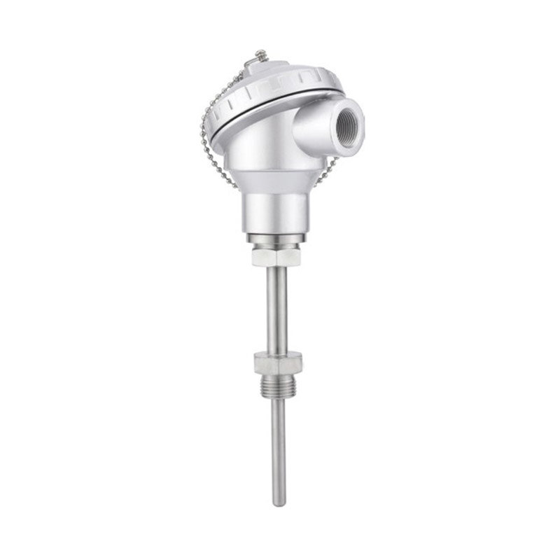
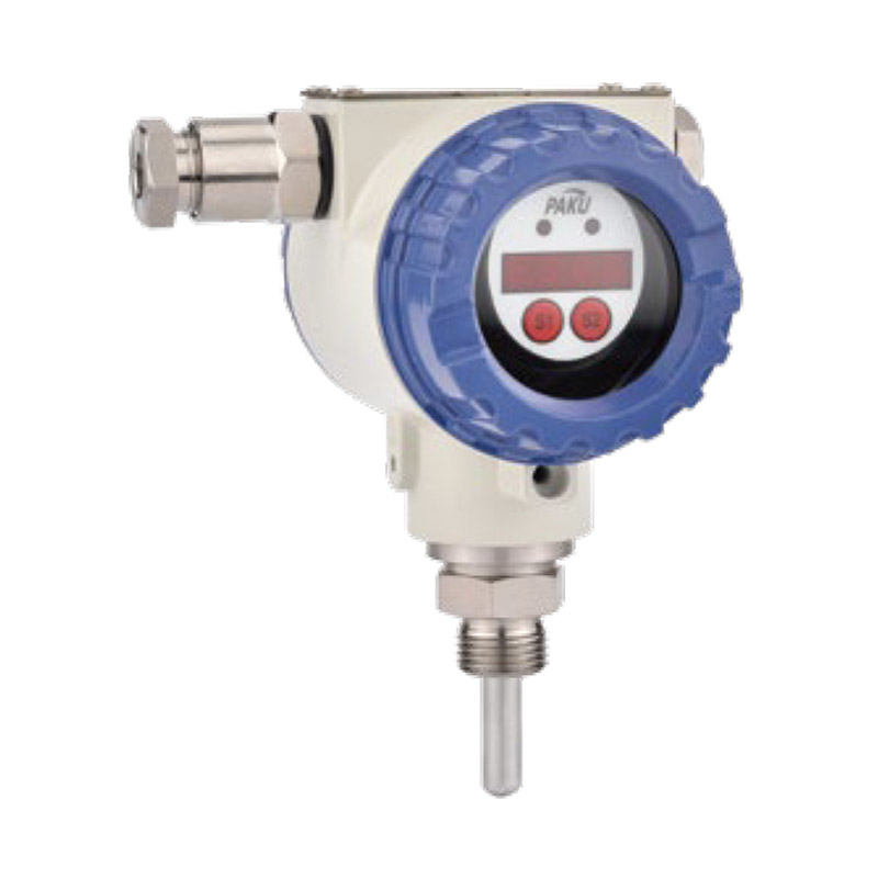
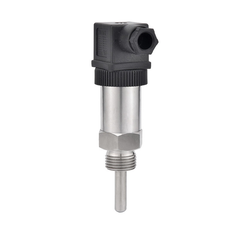
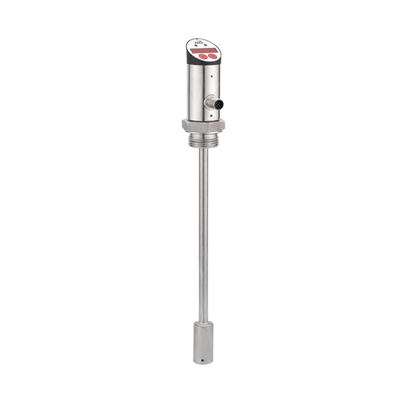
Head-mounted transmitters install directly on the sensor terminal head, minimizing wiring costs and providing excellent signal integrity. These models typically have an operating temperature range of -40°C to 85°C and offer IP67 or higher environmental protection. They are ideal for field installations where the sensor location is accessible for maintenance.
Rail-mounted (DIN-rail) transmitters install in control cabinets or junction boxes, allowing centralized configuration and maintenance. This configuration supports multiple sensor inputs in a single location and provides better protection in harsh environments. Field wiring connects sensors to the transmitter using extension cables, which must be properly selected to avoid measurement errors—for RTDs, use three-wire or four-wire configurations with matched cable resistance.
Selection Criteria for Industrial Applications
Technical Specifications Analysis
Selecting the appropriate transmitter requires evaluating multiple technical parameters against application requirements. Accuracy specifications should account for the entire measurement chain, including sensor tolerance, transmitter error, and ambient temperature effects. For example, a pharmaceutical application requiring ±0.5°C system accuracy might need a transmitter with ±0.1°C accuracy to compensate for sensor and installation uncertainties.
Response time becomes critical in dynamic processes where rapid temperature changes occur. Standard transmitters have response times of 1-2 seconds, while fast-response models achieve updates in 100-200 milliseconds. Consider also the transmitter's digital filtering capabilities, which can reduce noise but increase effective response time.
Environmental and Safety Considerations
Environmental ratings determine where transmitters can safely operate. Key certifications include:
- IP (Ingress Protection) ratings—IP65 for dust-tight and water-resistant, IP67 for temporary submersion protection
- Hazardous area certifications such as ATEX, IECEx, or FM/CSA for explosive atmospheres, with intrinsically safe models drawing less than 30 mA current
- SIL (Safety Integrity Level) ratings for safety-critical applications, with SIL 2 or SIL 3 certified models providing documented failure rates
- Vibration and shock resistance specifications, particularly important in rotating equipment or high-vibration environments
Communication Protocol Requirements
Modern transmitters offer various communication options beyond analog 4-20 mA output. HART protocol provides digital communication superimposed on the analog signal, enabling remote configuration and diagnostics without interrupting the control signal. HART-enabled transmitters constitute approximately 70% of new installations in process industries due to backward compatibility with existing analog systems.
Foundation Fieldbus and PROFIBUS PA protocols offer fully digital, multi-drop communication on a single cable pair, reducing wiring costs in large installations. These protocols support advanced diagnostics, including sensor drift detection, connection quality monitoring, and predictive maintenance alerts that can reduce unplanned downtime by up to 40% according to industry studies.
Installation Best Practices
Wiring and Grounding Guidelines
Proper wiring ensures accurate measurements and prevents electromagnetic interference. For 4-20 mA transmitters, use shielded twisted-pair cable with 18 AWG or larger conductors for runs up to 1000 meters. Connect the shield at one end only—typically at the control system ground—to prevent ground loops that can introduce noise and measurement errors.
RTD transmitters require special attention to lead wire resistance. Three-wire RTD configurations compensate for lead resistance when all leads have equal resistance, while four-wire configurations eliminate lead resistance effects entirely and should be used for high-accuracy applications requiring better than ±0.2°C precision. Use the same cable type and length for all RTD leads to maintain balanced resistance.
Configuration and Calibration Procedures
Initial configuration involves setting the temperature range, sensor type, engineering units, and damping values. Most transmitters support configuration via HART communicators, dedicated software, or local push-buttons. Document all configuration settings for future reference and maintenance activities.
Calibration verification should occur at installation and periodically during operation. A two-point calibration at 0% and 100% of range typically provides adequate accuracy for most applications. High-precision applications may require multi-point calibration at 0%, 25%, 50%, 75%, and 100% of span using certified reference standards traceable to national standards laboratories. Maintain calibration records to satisfy regulatory requirements and track drift patterns.
Common Installation Mistakes to Avoid
- Installing transmitters in locations exceeding their ambient temperature rating, which degrades accuracy and reduces lifespan
- Failing to weatherproof cable entries, allowing moisture ingress that causes corrosion and measurement drift
- Mixing sensor types without reconfiguring the transmitter, resulting in grossly inaccurate readings
- Running signal cables parallel to power cables for extended distances, introducing electromagnetic interference that can cause ±1-2% measurement error
- Neglecting to configure alarm and diagnostic functions that provide early warning of sensor or transmitter failures
Troubleshooting and Maintenance
Diagnostic Features and Fault Detection
Modern smart transmitters incorporate self-diagnostic capabilities that monitor transmitter health and sensor condition. Common diagnostics include sensor break detection, which drives the output to a configured alarm value (typically 3.6 mA or 21 mA) when the sensor circuit opens. Out-of-range detection alerts operators when measured temperatures exceed configured limits, indicating process upsets or sensor failures.
Advanced diagnostics track sensor drift by comparing current readings against historical baseline data. When drift exceeds configured thresholds—typically ±0.5°C to ±2°C depending on application criticality—the transmitter generates maintenance alerts, enabling predictive replacement before accuracy degrades beyond acceptable limits.
Systematic Troubleshooting Approach
When encountering measurement problems, follow a methodical diagnostic sequence. First, verify power supply voltage at the transmitter terminals—voltage should be between 10.5-42 VDC for loop-powered models. Next, measure the output current with a precision ammeter, confirming it falls within the expected range for the current process temperature.
If output current is correct but the control system shows incorrect values, check scaling and configuration parameters. If output current is incorrect, disconnect the sensor and measure its resistance or voltage directly. RTD resistance should match published tables—for example, a Pt100 RTD reads 100.0 ohms at 0°C, 138.5 ohms at 100°C. Significant deviation indicates sensor degradation requiring replacement.
Preventive Maintenance Schedule
Establish a maintenance program based on application criticality and environmental conditions. Typical schedules include:
- Monthly visual inspection of housing condition, cable connections, and terminal tightness
- Quarterly verification of output accuracy using portable calibrators or comparison against reference instruments
- Annual calibration verification with documented results, adjusting if error exceeds ±0.5% of span
- Three-year comprehensive calibration including linearity checks across the full measurement range
Critical applications such as pharmaceutical manufacturing or custody transfer may require more frequent verification to maintain regulatory compliance and measurement uncertainty within specified limits.
Industry-Specific Applications
Oil and Gas Production
Temperature transmitters in oil and gas applications must withstand extreme conditions while maintaining measurement integrity. Wellhead monitoring requires transmitters rated for continuous operation at temperatures up to 150°C and pressures exceeding 10,000 psi. Explosion-proof or intrinsically safe models with ATEX Zone 0 or IECEx ia certification are mandatory for installation in hazardous areas.
Pipeline monitoring systems employ transmitters with wireless communication capabilities to reduce installation costs in remote locations. These battery-powered units achieve 10-15 year operational life through power management algorithms that adjust sampling rates based on temperature stability.
Food and Beverage Processing
Sanitary applications require transmitters with 3-A, EHEDG, or FDA-compliant materials and construction. Stainless steel housings with smooth surfaces prevent bacterial growth and facilitate clean-in-place (CIP) procedures. Temperature control during pasteurization processes demands accuracy within ±0.3°C to ensure pathogen elimination while preserving product quality.
Fermentation monitoring uses transmitters with narrow-span configurations, measuring temperatures within small ranges like 15-25°C with enhanced resolution of 0.01°C. This precision enables tight control of enzymatic reactions that determine final product characteristics.
Power Generation
Steam turbine monitoring employs multiple transmitters measuring bearing temperatures, steam temperatures, and exhaust conditions. Redundant transmitter installations with voting logic provide fault tolerance in critical monitoring points. High-temperature models withstand continuous exposure to superheated steam at 565°C in advanced ultra-supercritical power plants.
Generator winding temperature monitoring uses RTD transmitters with Class A accuracy (±0.15°C at 0°C) to detect hot spots that indicate cooling system problems or insulation degradation. Early detection prevents catastrophic failures that could result in extended outages costing millions in lost revenue.
information
 [email protected]
![]() +86-13386111894 / +86-021-37566990
+86-13386111894 / +86-021-37566990
![]() B-4th Floor, Lane 1313, Nanting Road, Nanqiao Town, Fengxian District, Shanghai, China
B-4th Floor, Lane 1313, Nanting Road, Nanqiao Town, Fengxian District, Shanghai, China

Product Links