

 +86-13386111894
 Products & Solutions
 en
 English
 Русский
 España
 عرب .
If you need any help, please feel free to contact us
inquire
How Does a Pressure Sensor Work? Principles, Types, and Signal Outputs
A pressure sensor works by converting a physical pressure into an electrical signal. The signal is generated when a diaphragm or another elastic element deflects under pressure, and a sensing element translates that deflection into a change in resistance, capacitance, voltage, or frequency. The result is a measurable output that a PLC, transmitter, or gauge can read. This matters because most pressure problems in the field are not about the sensor's basic principle—they are about whether the chosen sensing technology, range, and signal output match the actual process conditions.
The Core Working Principle: From Pressure to Signal
The working principle can be broken into four stages. Each stage adds error, cost, or capability, so understanding them helps you specify the right device instead of guessing from a catalog headline.
- Pressure enters the sensor through a port and acts on a flexible diaphragm, piston, or bellows.
- The elastic element deflects by a small amount, often only a few micrometers at full scale.
- A sensing element attached to or integrated with the diaphragm converts that mechanical movement into an electrical parameter: resistance, capacitance, charge, or optical intensity.
- Signal conditioning electronics amplify, linearize, temperature-compensate, and convert the raw parameter into a standard output such as 4–20 mA, 0–10 V, or a digital bus reading.
For example, a piezoresistive sensor etches strain gauges into a silicon diaphragm. When pressure bends the diaphragm, the gauges stretch or compress, and their resistance changes. A Wheatstone bridge converts that tiny resistance change into a millivolt-level differential voltage. Without compensation, that voltage drifts with temperature; with compensation, it becomes a stable reading. This is why two sensors with the same pressure range can behave very differently in a hot or vibrating plant.
Sensing Technologies: How the Diaphragm Becomes a Signal
Several sensing technologies are common in industrial pressure instruments. The table below compares how they create a signal and where each one tends to fit.
| Technology | Physical Effect | Typical Output | Best For | Limitations |
| Piezoresistive | Strain gauges change resistance when the diaphragm bends | mV/V bridge, amplified V or mA | General industrial pressure, differential pressure, cost-sensitive OEM | Temperature sensitivity; requires compensation |
| Capacitive | Diaphragm movement changes the gap between capacitor plates | Capacitance change, then V or mA | Low pressure, high sensitivity, differential measurement | Sensitive to humidity and stray capacitance; more complex electronics |
| Piezoelectric | Quartz crystal generates charge under dynamic strain | Charge, high-impedance voltage | Fast dynamic pressure, combustion, shock waves | Cannot measure true static pressure for long periods |
| Optical | Pressure moves a mirror or fiber grating, changing light intensity or wavelength | Optical signal, then digital | Harsh electromagnetic environments, high-voltage areas | Higher cost; alignment and contamination concerns |
| MEMS | Micro-machined silicon diaphragm with integrated strain or capacitive elements | mV, digital, or ratiometric | Compact devices, medical, automotive, mass production | Limited media compatibility without isolation; small ports |
Piezoresistive and capacitive designs dominate process industries. Piezoelectric sensors are excellent for dynamic events but are a poor choice if you need a stable static reading for hours. Optical sensors can be useful where electromagnetic interference is severe, but they are rarely the lowest-cost option.PN501 Ceramic Piezoresistive Pressure Sensor/TransmitterCompact ceramic piezoresistive transmitter measuring gauge or absolute pressure up to 600 bar, suited to harsh industrial environments and pressure control.View Product →
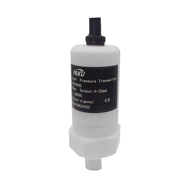
For example, Paku Sensors offers a ceramic piezoresistive pressure sensor, model PN501, which uses a ceramic diaphragm and thick-film resistors. Ceramic is more corrosion-resistant than some silicon designs and can handle abrasive or slightly aggressive media when the wetted parts are selected correctly.
Pressure Measurement Types: Absolute, Gauge, and Differential
The same physical sensor can be configured for different reference pressures. Choosing the wrong reference is one of the most common specification mistakes.
- Absolute pressure measures pressure relative to a sealed vacuum reference. It is used for barometric pressure, altitude, and sealed vessels where atmospheric changes must not affect the reading.
- Gauge pressure measures pressure relative to the local atmosphere. Most pump discharge, hydraulic, and compressed air readings are gauge pressures. A vented reference port is required, and a blocked vent will cause drift.
- Differential pressure measures the difference between two pressure ports. It is used for filter monitoring, flow measurement with an orifice plate, and level measurement in closed tanks.
If you order a gauge sensor for a sealed tank level application, the reading will change when the weather changes. If you order an absolute sensor for a pump discharge line, you will read approximately atmospheric pressure plus the actual line pressure, which may be acceptable but is not the same as gauge pressure. Always confirm the reference type before purchase.
From mV to 4–20 mA: Signal Outputs and What They Mean for Your System
The sensor's output must match the input of the controller or PLC. A raw millivolt signal is cheap and fast but travels only a short distance before noise becomes a problem. A 4–20 mA current loop can run hundreds of meters and is largely immune to electrical interference. A 0–10 V signal is common in building automation but suffers voltage drop over long cables. Digital outputs such as RS-485, HART, or IO-Link carry the measurement plus diagnostics and configuration data.PN30C High-Precision Single-Crystal Silicon Pressure TransmitterHigh-accuracy single-crystal silicon transmitter with isolated circuitry, digital communication options, and ranges from low differential pressure to 100 MPa.View Product →
For high-accuracy applications, a single-crystal silicon pressure transmitter with digital compensation can provide better long-term stability than a basic analog sensor. Paku Sensors' PN30C high-precision single-crystal silicon pressure transmitter is an example of this approach, targeting differential pressure and gauge pressure measurements where zero drift and temperature effects must be tightly controlled.
Also check the load resistance. A 4–20 mA transmitter may drive only 250 ohms if the supply voltage is 12 V, but 600 ohms at 24 V. If your PLC input has a 250-ohm sense resistor, the loop will work, but adding an isolator or a long cable may push the voltage beyond the transmitter's capability.
Practical Selection Factors That Decide Whether a Sensor Works Reliably
Pressure sensors fail in the field for predictable reasons: wrong range, wrong material, wrong reference, or wrong installation. The following factors matter more than the sensing principle itself.
- Range and overload: Choose a range where normal operating pressure sits between 30% and 70% of full scale. A sensor rated for 100 bar but operated at 95 bar will have poor accuracy and short life. Confirm the proof pressure and burst pressure.
- Accuracy and temperature error: A ±0.5% full-scale sensor may drift by ±1% over a 50 °C temperature change unless it is compensated. For critical batching, calculate the total error budget, not just the room-temperature accuracy.
- Wetted materials: 316L stainless steel is common, but ammonia, seawater, and some acids require ceramic, PTFE, or Hastelloy diaphragms. A chemical compatibility chart is not optional.
- Process connection: G1/4, 1/4 NPT, and flange connections are not interchangeable. A mismatched thread can leak or damage the port.
- Environmental rating: IP65 protects against water jets; IP68 allows temporary immersion. Hazardous areas require explosion-proof certification, such as Ex d or Ex ia.
For a deeper walkthrough of types, applications, and selection steps, see this pressure sensor selection guide. It covers how to match the sensor to the process instead of relying on a single datasheet number.
Installation, Media, and Failure Modes
Good installation prevents many apparent sensor faults. Mount the sensor where it can be isolated and bled. For liquid service, mount below the tap so air does not trap in the impulse line. For gas service, mount above the tap so condensate drains back into the pipe. Use a pigtail or siphon on steam lines to keep the sensor below the steam temperature limit.PN51C Micro Differential Pressure Sensor/TransmitterDiffused silicon micro differential pressure transmitter for low-range liquid and gas measurement, with 4-20 mA output, temperature compensation, requiring correct port orientation.View Product →
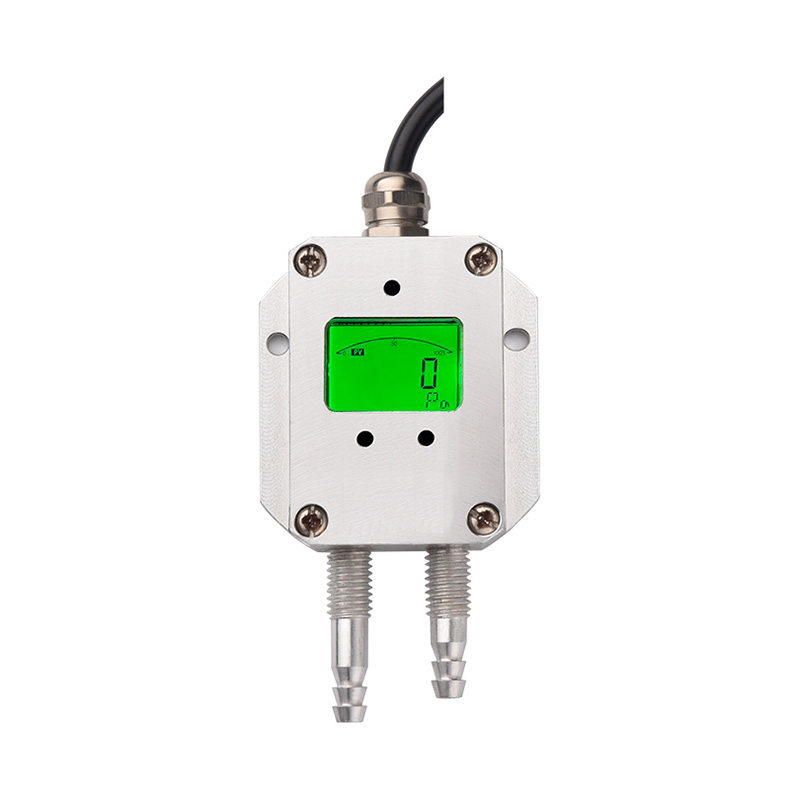
Differential pressure sensors are especially sensitive to installation errors. Reversed high and low ports will produce a negative reading and may damage the diaphragm if the differential exceeds the proof pressure. A micro differential pressure sensor such as the PN51C from Paku Sensors is designed for low-range differential measurement, but it still requires correct port orientation and gradual valve opening. Common failure modes include clogged impulse lines, frozen water in the sensing cavity, and vibration fatigue on unsupported capillary tubes.
If a sensor reads a constant value regardless of process changes, the problem is often a blocked port, a closed isolation valve, or a wiring short. If the reading drifts slowly, check temperature compensation, vented reference blockage, or diaphragm deformation from overpressure.
In short, a pressure sensor works by turning a mechanical deflection into an electrical signal, but the engineering value comes from matching the sensing element, reference type, output signal, and materials to the real process. That is what separates a reliable measurement from a recurring maintenance ticket. For answers to specific application questions, the technical FAQ and product documentation are useful references before you specify the next unit.
information
 [email protected]
 +86-13386111894 / +86-021-37566990
[email protected]
 B-4th Floor, Lane 1313, Nanting Road, Nanqiao Town, Fengxian District, Shanghai, China

Product Links