 en
en English
 Русский
 España
 عرب .
عرب .

If you need any help, please feel free to contact us
inquire
Liquid Level Sensing: Technologies, Selection Guide & Installation Tips
What Is Liquid Level Sensing
Liquid level sensing is the process of detecting, measuring, and monitoring the position or height of a liquid within a vessel, tank, pipe, or open channel. A liquid level sensor converts the physical presence or height of a liquid into an electrical signal that can be used to trigger alarms, control pumps and valves, feed data to a programmable logic controller, or display a continuous readout on a monitoring system.
The fundamental distinction in liquid level sensing is between point level detection and continuous level measurement. Point level detection answers a binary question: is the liquid above or below a specific threshold? This output is used to trigger events — activating a pump when a tank runs low, shutting a fill valve when the tank reaches capacity, or sounding an overflow alarm. Continuous level measurement answers a proportional question: exactly how much liquid is in the tank right now? This output is used for inventory management, process control, and dosing systems where knowing the precise level at every moment is essential to system performance.
Across industrial automation, liquid level sensing plays a foundational role in process safety and efficiency. An unmonitored tank that overflows causes environmental damage, product loss, and potential injury. A tank that runs dry can cavitate pumps, starve process lines, or halt production. Reliable level sensing eliminates both failure modes simultaneously, making it one of the most universally specified measurement functions in manufacturing, water treatment, chemical processing, food and beverage production, and energy management.
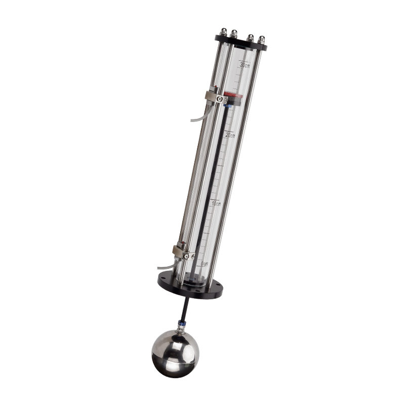
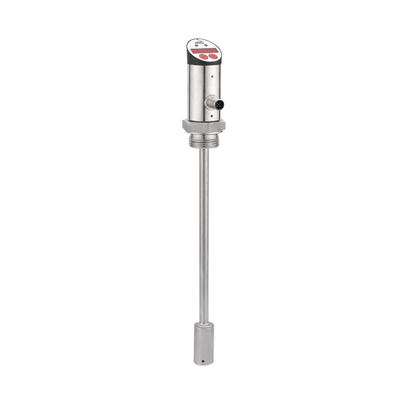
Float-Based Level Sensing
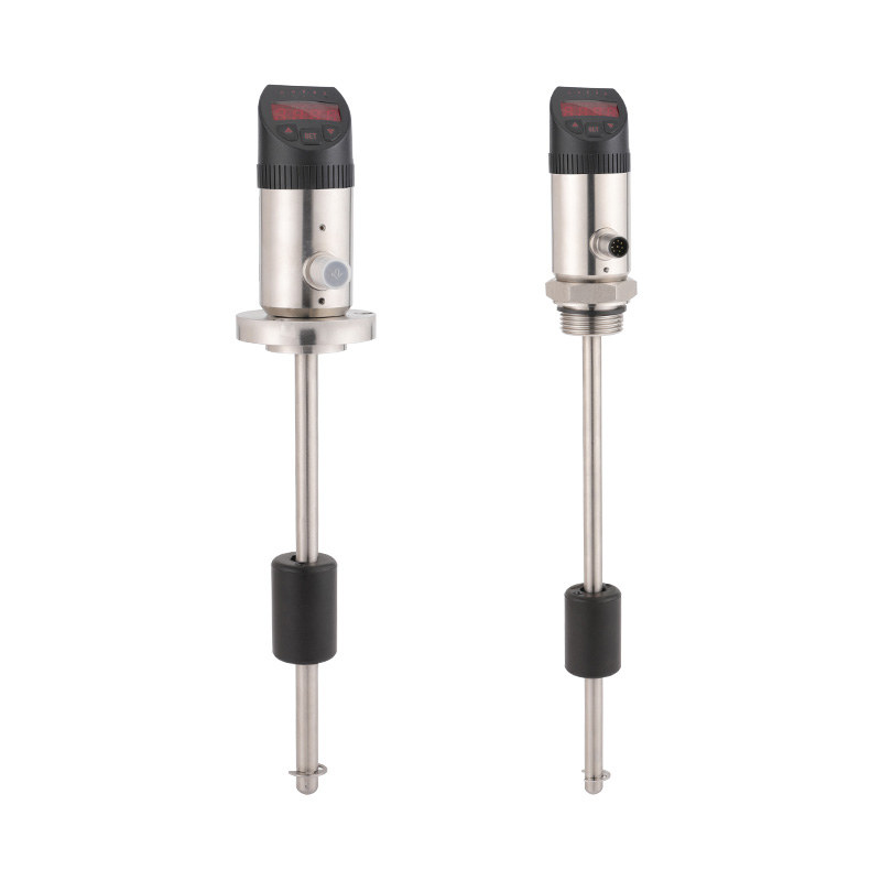
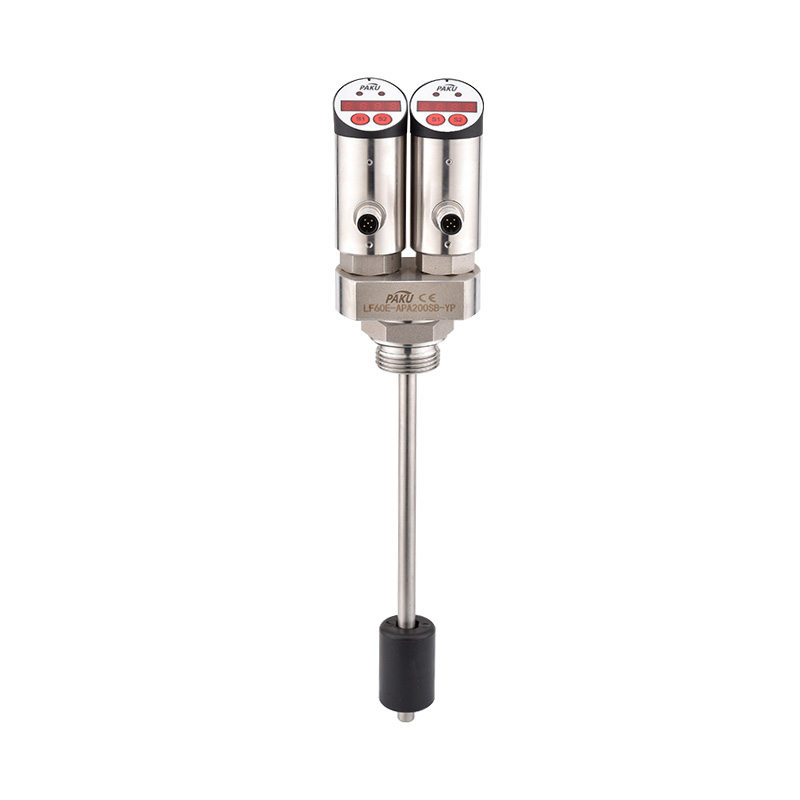
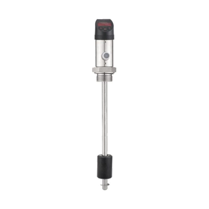
Float-based level sensing is one of the oldest and most widely deployed liquid level technologies, valued for its mechanical simplicity, direct contact detection, and independence from fluid electrical properties. A float — typically a hollow sphere or cylindrical body made from stainless steel, polypropylene, or other materials matched to the process fluid — rides on the liquid surface and moves vertically as the level rises or falls.
In the most common float switch configuration, the float body contains a permanent magnetic ring. As the float moves along a sealed non-magnetic stainless steel guide tube, the magnetic field triggers or releases a reed switch mounted inside the tube at the target level position. The reed switch opens or closes the electrical circuit, producing a discrete on/off signal with no external power required at the sensing element itself. This construction results in an inherently robust, spark-free switching mechanism suitable for use with flammable or explosive liquids when appropriately certified.
The practical advantages of float-based liquid level switches are significant: they function correctly across a very wide range of fluid types without calibration, they are unaffected by foam or vapor above the liquid surface, and they tolerate moderate levels of liquid contamination that would defeat optical or capacitive sensors. Their primary limitation is mechanical — the float must move freely, meaning highly viscous fluids, fluids with heavy suspended solids, or tanks with internal baffles that restrict float travel require alternative technologies. Float-based sensors are also inherently point-level devices; they cannot provide continuous level data without adding multiple switches at different heights or combining float sensing with a different measurement principle.
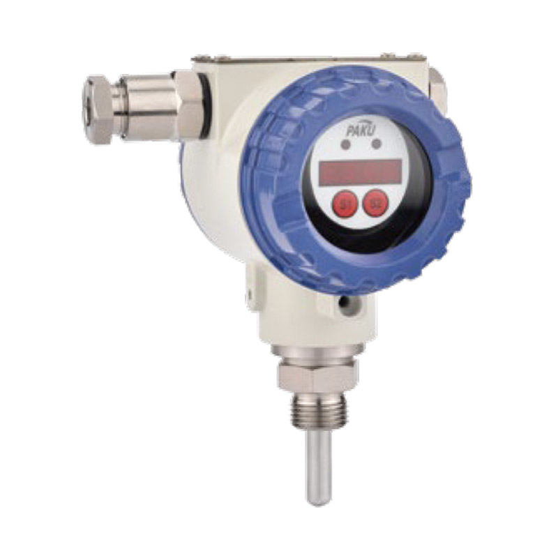
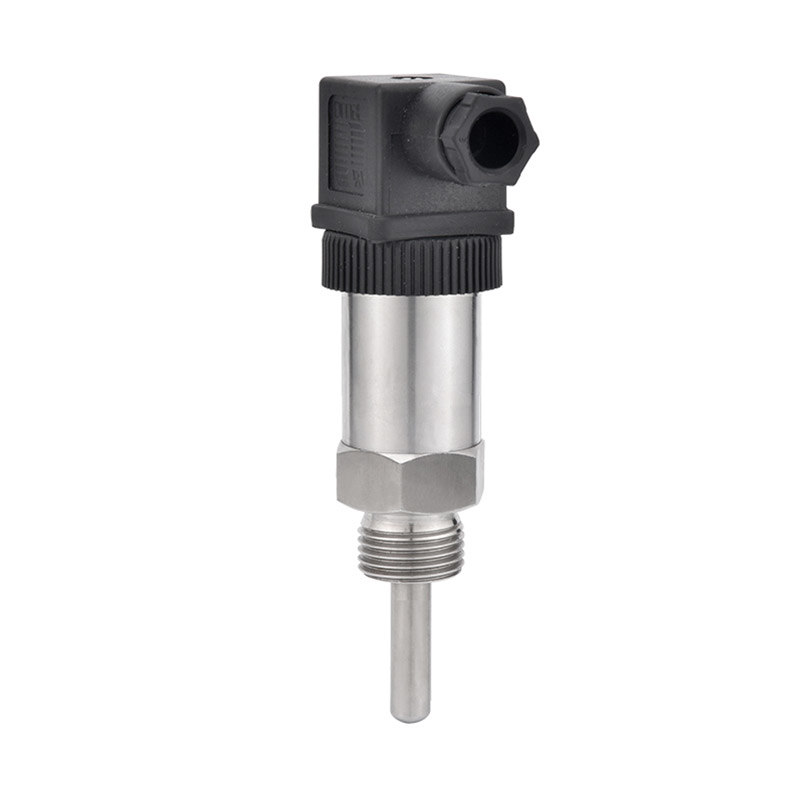
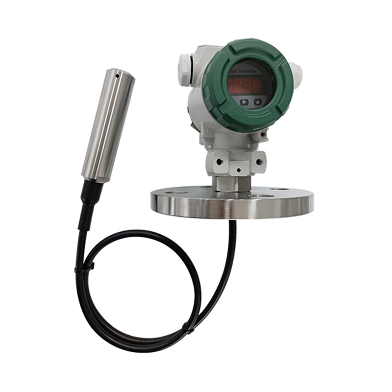
Hydrostatic Pressure Level Sensing
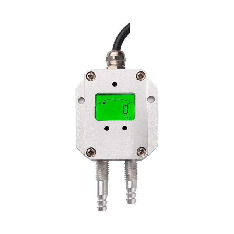
Hydrostatic pressure level sensing operates on the principle that the pressure exerted by a column of liquid at any given depth is directly proportional to the height of liquid above the measurement point and the density of the fluid. By measuring the pressure at the bottom of a tank or at a fixed submerged point, the sensor calculates the liquid height above it using the relationship: Pressure = fluid density × gravitational acceleration × liquid height.
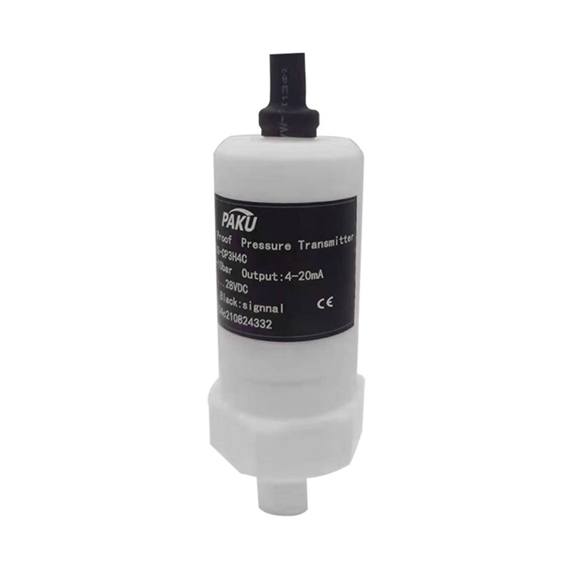
The most common implementation is a submersible static pressure transmitter — a sealed, liquid-proof sensor lowered into the tank on a cable and positioned at the lowest point of the measurement range. The sensing element, typically a diffused silicon piezoresistive element or a ceramic capacitive pressure cell, measures the absolute or gauge pressure at its location and transmits a proportional 4–20 mA signal to the control system. Because the signal is continuous and proportional to level height, hydrostatic transmitters provide the full-range continuous level data that point-level float switches cannot deliver.
A liquid level transmitter based on hydrostatic pressure is highly accurate — typically within 0.1 to 0.5% of full scale — and unaffected by the optical or electrical properties of the liquid. It works equally well in water, oil, chemical solutions, and food-grade liquids, provided the wetted materials are compatible with the process fluid. The key installation requirement is compensating for fluid density variations: a sensor calibrated for water at 20°C will read incorrectly if the fluid density changes due to temperature, concentration, or product changeover. Systems handling fluids of variable density require either manual recalibration or a differential pressure transmitter configuration that references a known density standard.
Capacitive Level Sensing
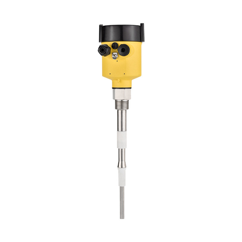
Capacitive level sensing exploits the difference in dielectric constant between the process liquid and the air or gas above it. A capacitive sensor forms one plate of a capacitor, with the vessel wall, a reference electrode, or the liquid itself forming the other plate. As the liquid level rises and submerges more of the sensor electrode, the effective dielectric constant between the plates changes, causing a measurable shift in capacitance that the sensor's electronics convert into a level signal.
The technology divides into two broad categories. Contact capacitive sensors are inserted into the tank, with the probe in direct contact with the liquid. They are extremely compact — a single rod electrode can provide continuous level measurement across its full insertion length — and respond quickly to level changes. Contact sensors are well-suited to tanks with limited access, conductive liquids, and applications requiring measurement in a very small vessel where ultrasonic or radar sensors cannot focus accurately.
Non-contact capacitive sensors measure level through the wall of the tank without any penetration. The sensor is mounted on the external surface of a non-metallic tank (plastic, glass, or ceramic), and the electric field passes through the tank wall to detect the liquid interface inside. This approach eliminates all wetted parts and all risk of leakage at a sensor penetration point — a major advantage in pharmaceutical, semiconductor, and food processing applications where tank integrity and contamination prevention are paramount. The limitation is that non-contact capacitive sensors require a non-conductive tank wall of consistent thickness, and their sensitivity is lower than contact designs, making them more suitable for point-level detection than continuous precision measurement.
Both contact and non-contact capacitive sensors are sensitive to the dielectric constant of the liquid being measured. A sensor calibrated for one fluid will read differently when exposed to a different fluid, even at the same physical level. Foam, condensation on the probe, and coating buildup can also shift the apparent capacitance and cause erroneous readings, requiring periodic cleaning or a self-calibrating design that compensates for gradual probe contamination.
Ultrasonic and Radar Level Sensing
Ultrasonic and radar level sensors are the two dominant non-contact continuous measurement technologies. Both work by emitting energy toward the liquid surface, measuring the time for the reflected signal to return, and calculating distance — and therefore level — from the time-of-flight measurement. Despite this shared operating principle, they differ significantly in their physics and practical performance characteristics.
Ultrasonic level sensors emit pulses of high-frequency sound (typically 40–200 kHz) from a piezoelectric transducer mounted above the liquid surface, pointing downward. The sound pulse travels through the air gap, reflects from the liquid surface, and returns to the transducer. Because the speed of sound in air varies with temperature, ultrasonic sensors include a temperature compensation function to maintain measurement accuracy across operating temperature ranges. Ultrasonic sensors are cost-effective, require no wetted parts, and are simple to install. Their primary limitations are sensitivity to airborne dust, foam on the liquid surface (which absorbs or scatters the sound pulse), vapor above volatile liquids, and high-pressure or high-temperature environments that affect acoustic propagation.
Radar level sensors emit microwave pulses (typically 6–80 GHz) that travel through the air gap and reflect from the liquid surface. Microwave signals are unaffected by temperature, pressure, vapor, dust, or most foam conditions that defeat ultrasonic sensors, making radar the preferred technology for challenging process environments — high-temperature vessels, pressurized tanks, volatile liquids, and outdoor applications subject to condensation and temperature extremes. Guided wave radar (GWR) variants route the microwave pulse along a probe rod or cable immersed in the liquid, further reducing the effect of surface turbulence and enabling accurate measurement in very low dielectric liquids such as hydrocarbons and solvents. Radar sensors carry a higher unit cost than ultrasonic designs, but their measurement reliability in difficult conditions justifies the premium in most industrial process applications.
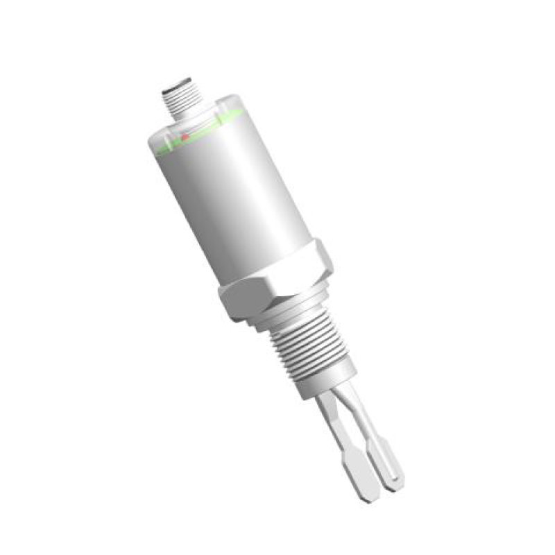
Optical and Tuning Fork Level Sensing
For point-level detection applications where simplicity, compact size, and high reliability are priorities, optical and tuning fork vibration sensors offer solid-state solutions with no moving parts and extremely long service lives.
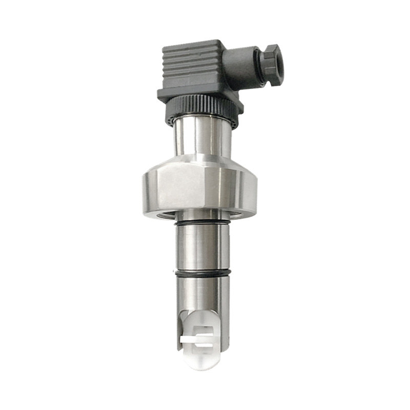
Optical level switches use an infrared LED and a phototransistor housed within a glass or polysulfone prism tip. When the sensor tip is in air, total internal reflection causes the infrared light to reflect from the prism surfaces back to the detector, maintaining a high signal level. When the prism is immersed in liquid, the refractive index difference between the prism and liquid reduces total internal reflection, causing light to escape through the prism tip rather than returning to the detector. The detector registers a signal drop and the sensor switches state. Optical sensors respond in milliseconds, are unaffected by vibration, require no calibration for the fluids they are designed for, and are compact enough to be installed in very small vessels. They are, however, sensitive to coating: an oil film, mineral deposit, or biological growth on the prism tip that bridges the air-to-liquid boundary will cause the sensor to indicate liquid presence even in an empty vessel.
Tuning fork vibration level switches operate on a different principle. Two tines extend from the sensor body and are driven to vibrate at their natural resonant frequency by a piezoelectric element. When the tines are immersed in liquid, the added mass and damping effect of the fluid shifts the resonant frequency and amplitude — a change detected by the sensor's electronics, which triggers a switching output. Tuning fork sensors are highly reliable in applications involving foamy liquids, where optical sensors fail due to foam coating the prism, and in granular or powdery media. They function correctly across a wide range of liquid densities and viscosities without recalibration, and their sealed stainless steel construction is compatible with hygienic, high-pressure, and aggressive chemical service applications.
Choosing the Right Level Sensing Technology
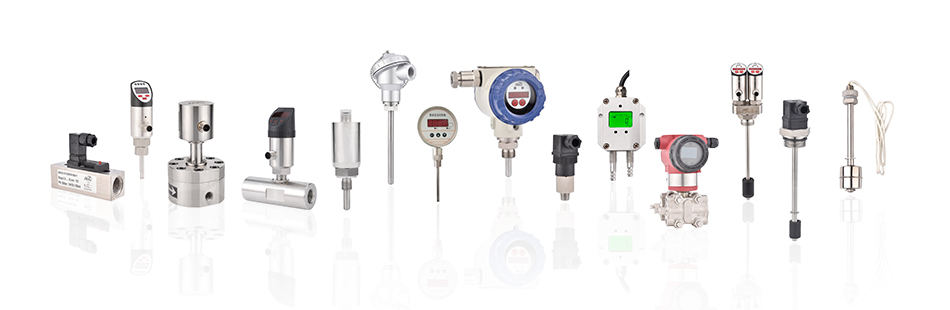
No single liquid level sensing technology is optimal for all applications. The correct choice emerges from systematically evaluating four factors: the properties of the liquid, the required measurement type and accuracy, the installation environment, and the output signal required by the control system. Browsing PAKU's complete liquid level series alongside this framework helps narrow the selection quickly.
| Technology | Measurement Type | Best Fluid Conditions | Avoid When | Typical Accuracy |
|---|---|---|---|---|
| Float switch | Point level | Clean, low-viscosity liquids | High viscosity, suspended solids | Fixed point (±position tolerance) |
| Hydrostatic pressure | Continuous | Most liquids, wide density range | Variable density without compensation | 0.1–0.5% FS |
| Capacitive (contact) | Point or continuous | Conductive or high-dielectric liquids | Coating-prone, low-dielectric fluids | 1–3% FS |
| Capacitive (non-contact) | Point level | Any liquid in non-metallic tanks | Metal tanks, very low dielectric | Point detection only |
| Ultrasonic | Continuous | Clean liquid surfaces, open tanks | Foam, vapor, high pressure/temp | 0.1–0.25% FS |
| Radar | Continuous | Challenging conditions, volatile fluids | Very low dielectric (use GWR) | ±1–2 mm |
| Optical | Point level | Clean, transparent or opaque liquids | Coating liquids, viscous oils | Point detection only |
| Tuning fork | Point level | Foamy, viscous, or granular media | Very high-viscosity adhesives | Point detection only |
Beyond the fluid and measurement type, consider the operating temperature and pressure of the installation. Float switches and optical sensors rated for standard service conditions (up to 130°C, 5 bar) are unsuitable for high-pressure steam vessels or cryogenic applications. Hydrostatic and radar sensors cover the widest environmental range in their respective categories. For hazardous area installations involving flammable or explosive liquids and vapors, confirm that the selected sensor carries the appropriate ATEX, IECEx, or regional explosion-protection certification before specifying.
Output Signals and System Integration
The electrical output of a liquid level sensor determines how it integrates with the broader control system. Matching the sensor output to the controller input type is as important as matching the sensing technology to the fluid — a technically excellent sensor producing the wrong output signal format requires additional signal conditioning that adds cost, latency, and potential failure points.
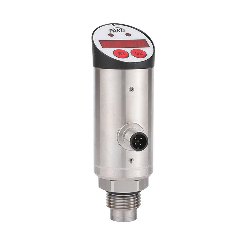
Discrete switching outputs (NPN or PNP transistor, or relay contact) are the standard output of point-level sensors — float switches, optical switches, and tuning fork switches. The sensor output changes state (open to closed, or high to low) when the liquid reaches the detection point. NPN and PNP outputs connect directly to PLC digital input modules; relay contact outputs are used where electrical isolation between the sensor and the control circuit is required, or where the sensor must switch AC power loads directly.
Analog 4–20 mA current loop output is the industry standard for continuous level transmitters. The transmitter sources a current proportional to the measured level — 4 mA corresponding to 0% of the measurement range and 20 mA corresponding to 100%. The current loop format is inherently noise-immune over long cable runs (unlike voltage signals that attenuate with distance and pick up electromagnetic interference), and the 4 mA live-zero signal allows the control system to distinguish between a sensor at 0% level and a broken or disconnected sensor circuit (which would read 0 mA). Most PLC analog input modules accept 4–20 mA directly, making integration straightforward.
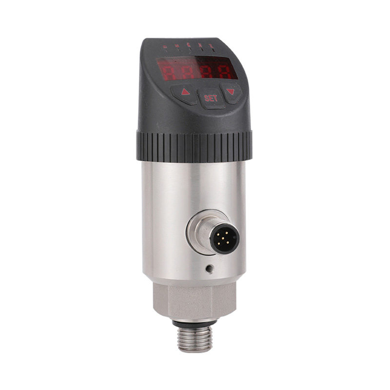
IO-Link digital communication is a newer interface standard gaining rapid adoption in industrial sensor applications. An IO-Link level sensor transmits measurement data, sensor status, diagnostic information, and configuration parameters over a standard three-wire connection to an IO-Link master module. Unlike analog signals, IO-Link transmits precise digital values unaffected by cable resistance or electromagnetic interference, and the bidirectional communication allows the control system to remotely configure sensor parameters, read diagnostic data, and perform remote calibration — eliminating the need for manual access to the sensor in hazardous or difficult-to-reach locations. IO-Link also enables the integration of a single sensor cable to carry both the primary level measurement and multiple auxiliary signals (temperature, error flags, maintenance alerts), reducing wiring costs in complex installations.
Installation Tips and Common Mistakes
Even the most precisely specified liquid level sensor will underperform if installed incorrectly. The following installation and maintenance practices address the most frequent causes of field measurement problems.
Avoid installing sensors in turbulent zones. Inlet pipes, agitator discharge zones, and pump suction areas create surface turbulence that causes erratic readings in ultrasonic sensors (due to signal scattering from surface waves) and mechanical stress on float sensors (due to repetitive impacts against guide tubes). Position sensors in a calm zone of the tank, away from inlets and agitators. Where tank geometry makes this difficult, install a stilling well — a vertical pipe with small holes at the bottom, open at the top, that equalizes with the main tank level while dampening surface turbulence inside the tube.
Account for fluid density in hydrostatic transmitter calibration. A hydrostatic level transmitter calibrated for water (density 1.0 g/cm³) will read approximately 20% low when measuring a fluid with a density of 1.2 g/cm³ at the same physical level, because the denser fluid exerts more pressure per unit height. Always recalibrate after any fluid change, and document the density assumption used in each calibration for future reference.
Inspect and clean optical and capacitive sensor tips regularly. Both technologies are sensitive to coating buildup on the sensing surface. In applications with oily, sticky, or mineral-rich fluids, establish a cleaning interval based on observed coating rates rather than a fixed calendar schedule. Optical sensors with self-diagnostic output will typically indicate a dirty-probe condition before the coating causes false switching — use this diagnostic signal to drive a condition-based maintenance approach rather than time-based cleaning.
Protect cable entry points on submersible transmitters. The most common failure mode for submersible hydrostatic transmitters is water ingress through the vent tube — a small capillary tube inside the cable that equalizes the reference side of the pressure sensor to atmospheric pressure. If this tube is blocked by condensation, contamination, or an improper conduit seal, the transmitter will drift as ambient pressure changes and eventually fail. Route the vent tube cable end to a dry, protected location and never seal the vent end into a waterproof conduit fitting.
Verify float freedom of movement before commissioning. For float-based sensors, physically confirm that the float moves smoothly along its full travel range before filling the tank. A float that sticks at any point due to a misaligned guide tube, a burr on the tube surface, or interference with internal tank structures will produce a stuck-at-one-state output that can be misdiagnosed as an electrical fault. Pre-commissioning mechanical verification takes minutes and prevents difficult troubleshooting after the tank is in service.
information
 [email protected]
![]() +86-13386111894 / +86-021-37566990
+86-13386111894 / +86-021-37566990
![]() B-4th Floor, Lane 1313, Nanting Road, Nanqiao Town, Fengxian District, Shanghai, China
B-4th Floor, Lane 1313, Nanting Road, Nanqiao Town, Fengxian District, Shanghai, China

Product Links