 en
en English
 Русский
 España
 عرب .
عرب .

If you need any help, please feel free to contact us
inquire
Float Switch for Sump Pumps: How It Works, Types & Selection Guide
What Is a Float Switch and How Does It Work in a Sump System
A float switch is a level-sensing device that automatically starts or stops a sump pump based on the water level in the pit. It is the primary control element in most residential and industrial sump systems, converting a simple mechanical movement—rising or falling water—into a reliable electrical signal.
The operating principle is straightforward. The switch body floats on the water surface or is suspended in the liquid. As water rises, the float pivots or lifts. Inside the sealed housing, a steel ball rolls toward one end of the chamber under gravity, closing (or opening) a set of electrical contacts. This triggers the sump pump motor, draining the pit. When the water drops below the set point, the float returns to its resting angle, the ball rolls back, and the circuit opens, switching the pump off.
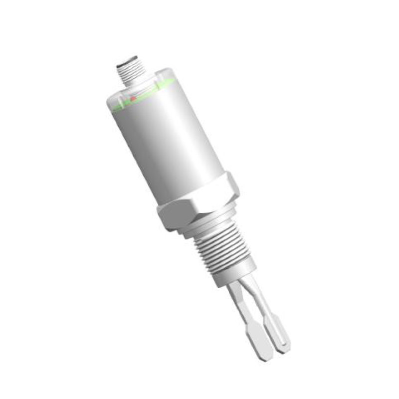
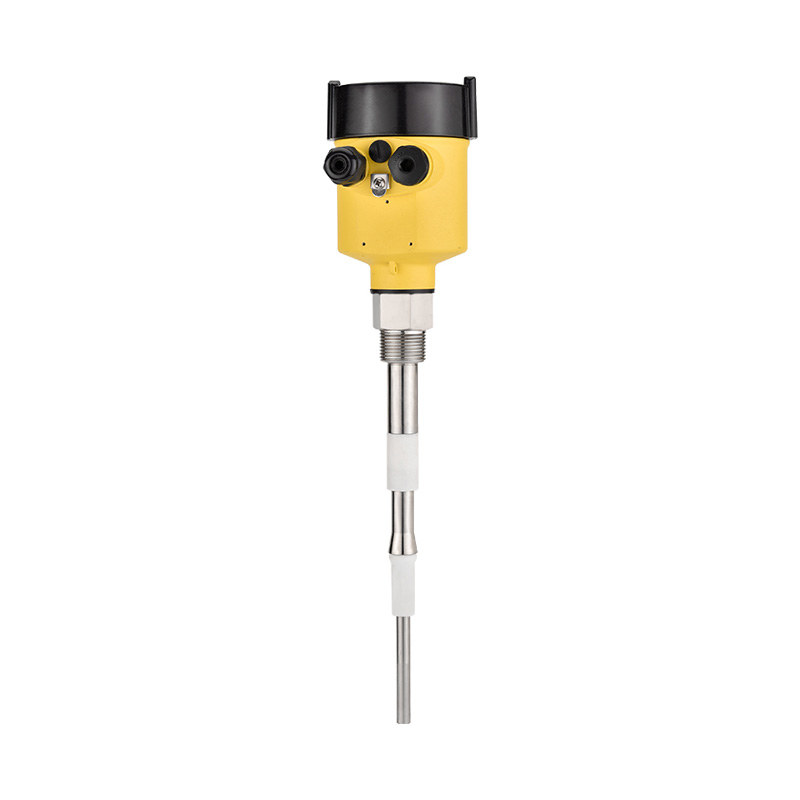
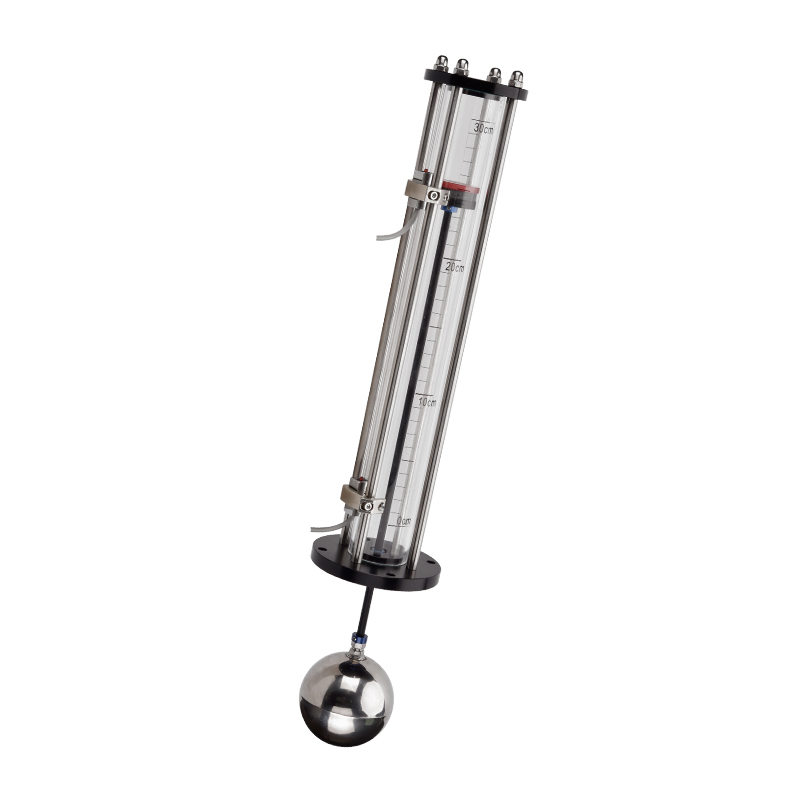
In industrial-grade designs, a reed switch is installed inside a sealed non-magnetic tube while an annular magnetic ring sits inside the float body. As the float rises or falls, the magnetic ring moves with it, triggering or releasing the reed switch with no mechanical contact between the electrical and wetted components. This construction delivers long service life and high resistance to corrosive media—critical for applications beyond simple groundwater drainage, such as wastewater collection, chemical storage, and process tanks.
Selecting the correct liquid level switch for a sump application depends on understanding these working principles, because different float designs behave differently under varying basin sizes, fluid types, and required switching frequencies.
Types of Float Switches for Sump Pumps
Not all sump float switches are interchangeable. The three main designs each suit different installation environments and control requirements.
| Type | Operating Principle | Best For | Key Limitation |
| Tethered Float Switch | Float pivots on a cord anchored to the pump or discharge pipe; cord length sets on/off levels | Wide basins (>300 mm diameter); high-volume residential and light commercial sump pits | Requires generous lateral space; can snag on pit walls in narrow installations |
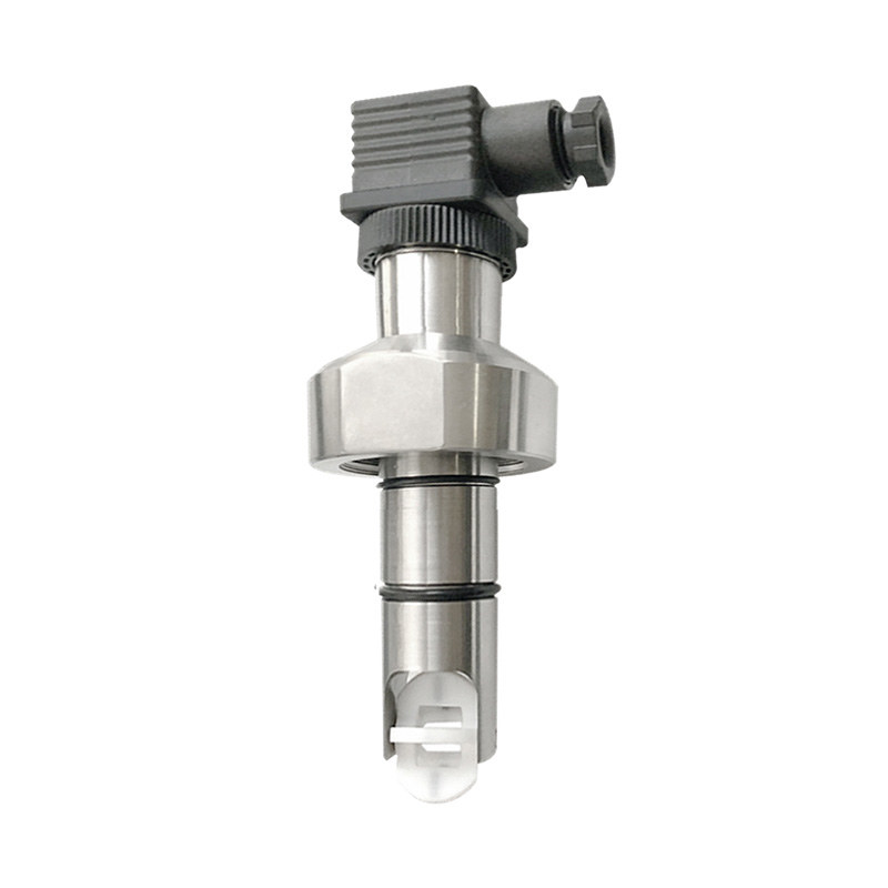
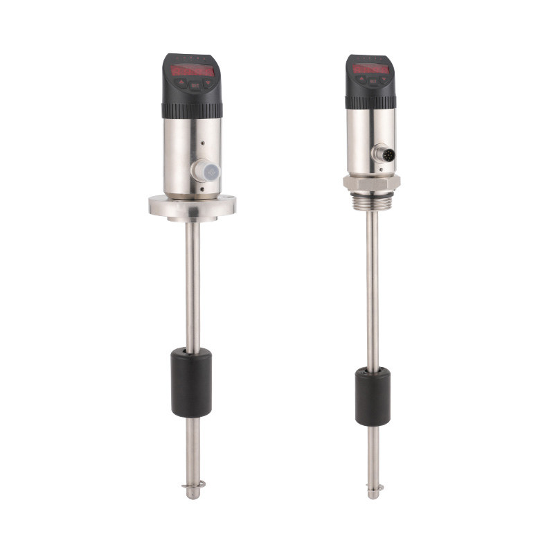
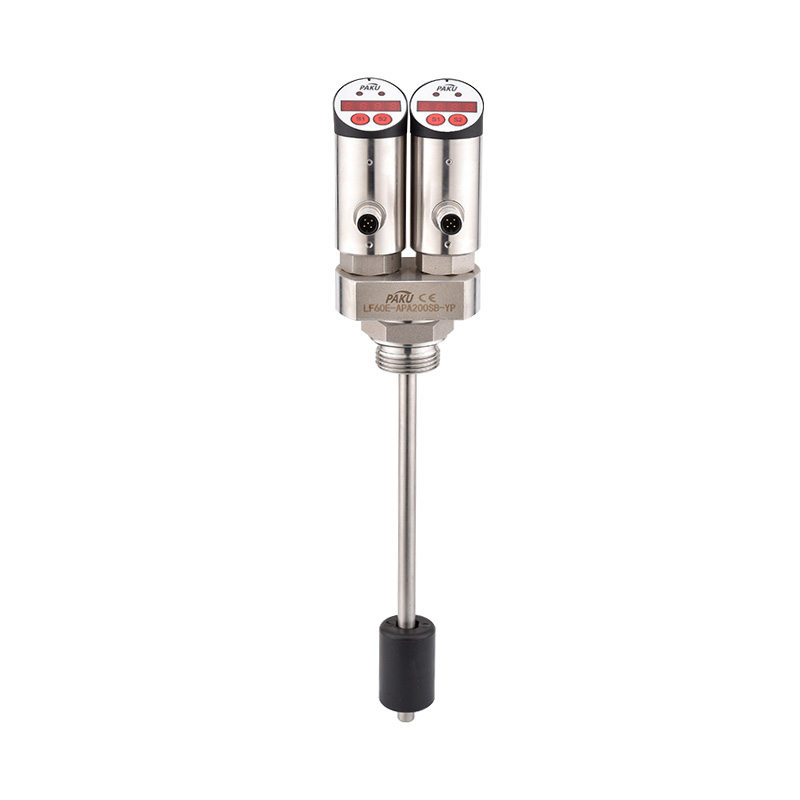
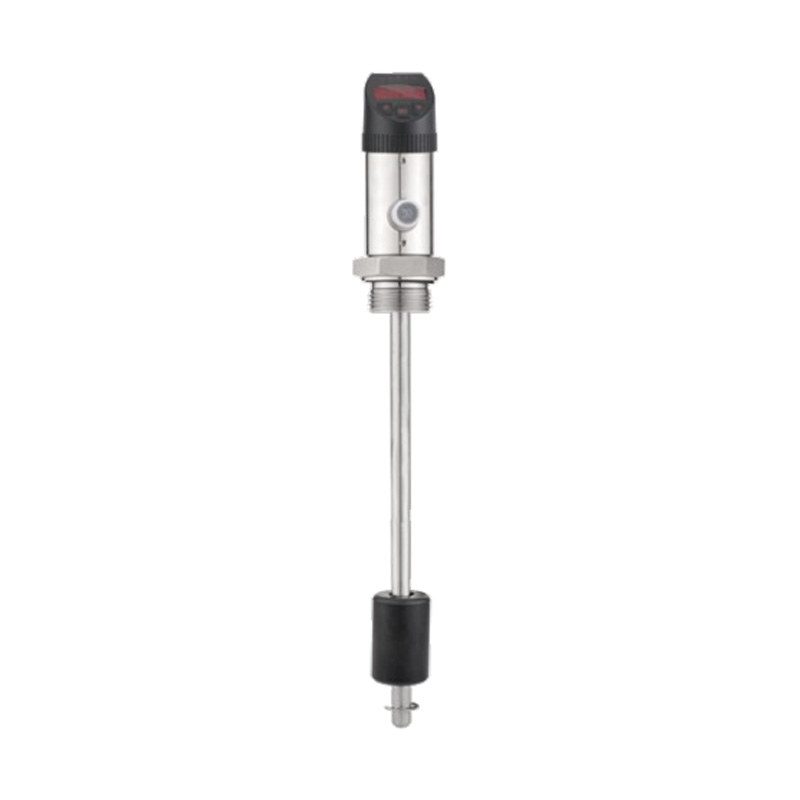
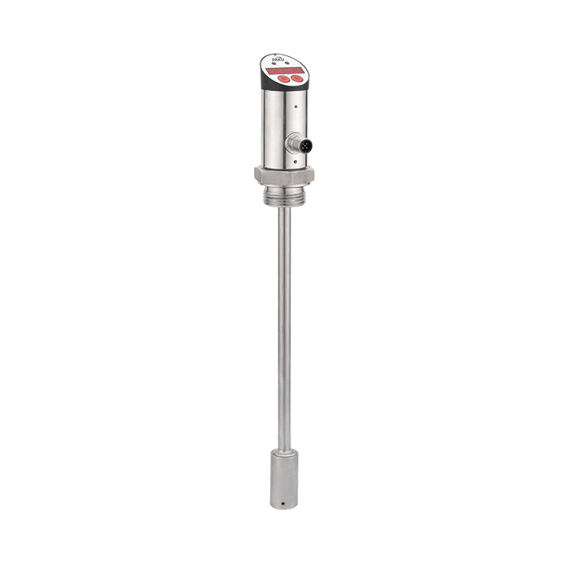
| Vertical Float Switch | Float slides vertically along a fixed guide rod; activates at set positions on the rod | Narrow pits; tight installations; sewage and effluent systems | Shorter differential range between on and off levels |
| Cable Float Switch (Reed Type) | Sealed float on a flexible cable; magnetic reed switch inside triggers with float angle | Industrial tanks; corrosive media; remote mounting; multi-point level control | Requires IP-rated cable entry; cable length must match tank depth |
Beyond mechanical design, float switches are also classified by their circuit action. A normally open (pump-down) switch has an open circuit at rest and closes when the water rises—standard for sump pumps that empty a pit. A normally closed (pump-up) switch passes current at rest and opens when the liquid reaches the high set point, used when a pump is filling a tank and must stop at maximum capacity. Fitting the wrong circuit action to a sump pump will result in either continuous running or complete failure to activate—both damaging outcomes.
Key Selection Criteria for Sump Float Switches
Choosing the right float switch requires matching the device specification to both the pump it controls and the environment in which it operates. The following parameters are the most critical.
Current and Voltage Rating
The float switch must be rated to handle the full running current of the sump pump motor. Most residential submersible sump pumps draw between 5 A and 15 A at 115–230 VAC. Using an undersized switch causes contact arcing, overheating, and premature failure. Always verify the switch's ampere rating against the pump nameplate data, not just the nominal horsepower.
Cable Length
The free cable between the anchor weight and the float body determines the differential—the vertical distance between the pump-on and pump-off levels. A longer free cable means the pump runs longer each cycle, which reduces the number of start/stop cycles per hour and allows bearings to cool between runs. Cable lengths from 2 m to 10 m are standard; deeper pits and industrial tanks require longer supply cables from float to control panel.
Protection Grade (IP Rating)
Sump pits are wet, often dirty environments. A minimum of IP68 protection—continuous immersion rated—is the practical standard for submerged float switches. For sewage or chemically contaminated sumps, the housing material (PP, PVDF, or stainless steel) matters as much as the IP rating. The anti-corrosion float switch series is specifically engineered for media where standard polypropylene housings would degrade.
Medium Compatibility and Temperature Range
Groundwater sump applications are benign, but the same float switch technology is deployed in acid drainage, cooling tower blowdown, chemical wash sumps, and heating system expansion tanks. Always confirm the float material's chemical resistance against the actual medium. Reed-switch designs with sealed stainless steel tubes offer broader medium compatibility because the electrical components never contact the fluid. Operating temperature ranges of −10 °C to 130 °C cover the majority of industrial sump scenarios.
Basin Diameter
Tethered switches need horizontal clearance to arc through their full travel. If the sump pit is narrower than approximately 300 mm, a vertical or cable-type float switch is the safer choice to prevent the float from jamming against the pit wall—a common cause of pump failure to activate during flooding events.
Installation and Adjustment Tips
Correct installation is as important as correct product selection. The following practices ensure reliable long-term operation.
- Anchor the cable securely. For tethered switches, attach the anchor weight or hose clamp to the discharge pipe at the correct height before connecting the pump power cord. The mounting point determines the pivot center of the float's arc—changing it shifts both the on and off levels simultaneously.
- Set the free cable length before installation. Determine the desired pump-on water depth and calculate the free cable length required to allow the float to reach horizontal (switching) position at that depth. Document this setting so it can be reproduced after any maintenance.
- Verify clearance from pump and pit walls. The float must swing freely through its full arc without contacting the pump body, discharge pipe, or pit walls. Test this manually by lifting the float to its activation angle with the pit empty before energizing the system.
- Do not mix grease types near sealed cable entries. Contaminating IP-rated cable glands with incompatible compounds can compromise the ingress protection seal. Use only manufacturer-recommended compounds if any sealing compound is required at the entry point.
- Test the full cycle before closing the pit. Fill the sump to above the on-level and confirm the pump starts automatically. Allow it to drain to below the off-level and confirm the pump stops. Only commission the system after a complete verified cycle—not just a bench continuity test.
For applications requiring monitoring of multiple levels simultaneously—alarm float, pump float, and overflow float in the same pit—a liquid level sensor with continuous output can complement discrete float switches to give the control system a full picture of pit conditions.
Common Float Switch Problems and How to Fix Them
Most float switch failures are predictable and preventable. Understanding the failure modes allows maintenance teams to address root causes rather than simply replacing parts.
Float Stuck in the On Position (Pump Runs Continuously)
The most frequent failure mode. Debris, scale, or grease accumulates around the float body or cable, preventing the switch from pivoting back to its off position after the water level drops. The result is continuous pump operation, accelerated motor wear, and risk of deadheading. Fix: Remove the float switch and clean all surfaces. In pits with high sediment loads, increase inspection frequency to quarterly and consider switching to a sealed vertical design less susceptible to fouling.
Float Stuck in the Off Position (Pump Fails to Activate)
The float is physically blocked from rising, typically by the same debris accumulation, or by the anchor weight slipping and shortening the free cable length to zero. This failure mode is dangerous because the sump fills without the pump activating. Fix: Inspect the anchor point at every service interval and ensure the free cable length matches the documented setting. Install a high-water alarm float as a secondary protection layer.
Rapid Cycling (Short On/Off Intervals)
If the pump starts and stops every few seconds, the free cable is too short—the differential between on and off water levels is insufficient for the inflow rate. Increase the free cable length to allow the pump to run long enough to lower the water level well below the switch-off point before inflow restores it. Rapid cycling overheats motors and reduces pump life dramatically.
Contact Wear and Voltage Drop
In high-cycle applications, the internal reed switch or ball contacts degrade over time, causing increased resistance and voltage drop to the pump motor. This presents as the pump running slowly or failing to reach full pressure. Check contact condition with a multimeter: resistance across a closed switch should be less than 1 Ω. Replace the float switch if resistance is higher or if pitting is visible on contacts.
Cable Jacket Degradation
Prolonged exposure to corrosive media, UV light (in open installations), or extreme temperatures accelerates jacket cracking. Cracked cable jackets allow moisture ingress into the switch body, eventually shorting the reed contacts. In corrosive environments, inspect cable condition at each service visit and replace the switch proactively at the first sign of jacket damage—before an electrical fault develops.
Reliable Level Control Starts with the Right Float Switch
A sump float switch is a simple device that carries significant responsibility: protecting basements, equipment rooms, and industrial facilities from flooding. Selecting the correct type, rating the switch accurately for the connected pump, and installing it with proper clearances and cable length are the three actions most likely to deliver years of trouble-free operation.
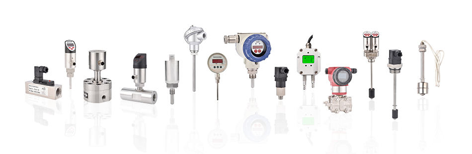
PAKU Sensors, a brand of Shanghai Kayuan Electronic Technology Co., Ltd., manufactures a comprehensive range of float type liquid level switches covering standard, anti-corrosion, compact, cable, and built-in configurations. Products are rated to IP65 and above, cover medium temperatures from −10 °C to 130 °C, and are available for OEM and ODM cooperation. PAKU level switches are deployed across water treatment, chemical processing, petroleum equipment, and industrial automation systems in more than a dozen countries. Contact the PAKU team to discuss the right float switch specification for your sump or liquid level control application.
information
 [email protected]
![]() +86-13386111894 / +86-021-37566990
+86-13386111894 / +86-021-37566990
![]() B-4th Floor, Lane 1313, Nanting Road, Nanqiao Town, Fengxian District, Shanghai, China
B-4th Floor, Lane 1313, Nanting Road, Nanqiao Town, Fengxian District, Shanghai, China

Product Links