 en
en English
 Русский
 España
 عرب .
عرب .
If you need any help, please feel free to contact us
inquire
Capacitive & Non-Contact Level Sensors: How They Work & How to Choose
What Are Capacitive Level Sensors?
A capacitive level sensor is an electronic measurement device that detects the level of liquids, solids, or slurries by measuring changes in electrical capacitance. When the level of a material rises or falls near the sensor probe, the capacitance between the probe and a reference electrode changes — and the sensor converts that change into a precise level reading or switching signal.
The underlying physics is straightforward: capacitance depends on the dielectric constant of the material between two conductive surfaces. Air has a dielectric constant of approximately 1, while most liquids and bulk solids have significantly higher values — water sits at around 80, while oils, grains, and powders range from 2 to 30. As the measured medium displaces air around the probe, capacitance increases proportionally, giving the sensor a reliable, continuous signal tied directly to material level.
This operating principle makes capacitive level sensors exceptionally versatile: a single sensor design, with appropriate calibration, can measure water, oils, adhesives, granular solids, and even certain powders — without mechanical moving parts and with no physical contact between the electronics and the process medium in many configurations.
Non-Contact Level Sensors: An Overview of the Technology
Non-contact level sensors measure material level without any physical element touching the process medium. The sensor transmits energy — ultrasonic sound waves, radar (microwave) signals, or laser pulses — toward the surface of the material and measures the time it takes for the reflected signal to return. This time-of-flight measurement is converted into a distance, and therefore a level reading, with high accuracy.
Non-contact technology eliminates the wear, contamination, and maintenance challenges inherent in immersed or contact-type sensing. For applications involving corrosive chemicals, high-viscosity fluids that coat probes, sticky bulk solids, or hygienic processes where sensor contact risks contamination, non-contact measurement is not merely preferable — it is often the only viable option.
The three dominant non-contact technologies each have distinct performance profiles: ultrasonic sensors offer cost-effective measurement in most standard liquids and solids; guided wave radar provides excellent performance in challenging media but requires a probe that contacts the fluid; and free-space radar (FMCW) combines true non-contact operation with the ability to measure through vapors, dust, and foam that defeat ultrasonic units.
Capacitive vs. Non-Contact Level Sensors: Choosing the Right Technology
Both capacitive and non-contact level sensors serve the same fundamental purpose — accurate level measurement — but their operating principles lead to very different strengths and limitations. The table below summarizes the key differences.
| Criteria | Capacitive Level Sensor | Non-Contact Level Sensor |
|---|---|---|
| Contact with Medium | Yes (probe immersed) | No |
| Suitable for Corrosive Fluids | With correct probe material | Yes — no wetted parts |
| Continuous Output | Yes | Yes |
| Affected by Foam/Vapor | Minimal | Ultrasonic: Yes / Radar: No |
| Hygienic / Sanitary Use | Limited | Excellent |
| Measurement Range | Up to ~10 m | Up to 70 m (radar) |
| Cost | Low–Moderate | Moderate–High |
The decision between the two technologies is rarely about accuracy — both can achieve measurement uncertainties below 1% of full scale when correctly applied. It is primarily driven by process conditions: whether the sensor can physically contact the medium, the nature of the surface being measured, and the environmental factors present in the vessel or silo.
How Capacitive Level Sensors Work in Detail
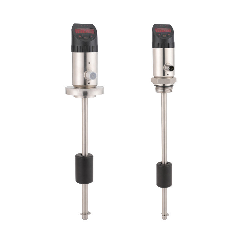
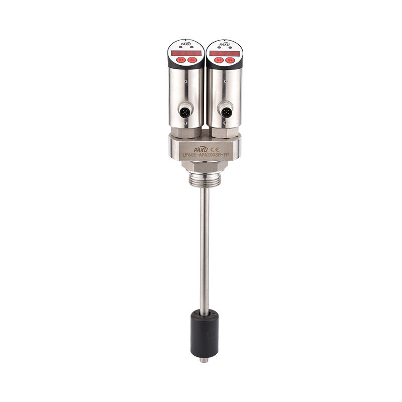
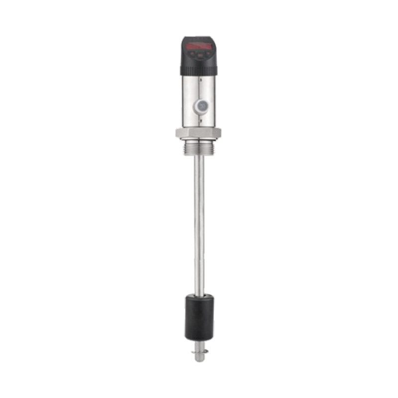
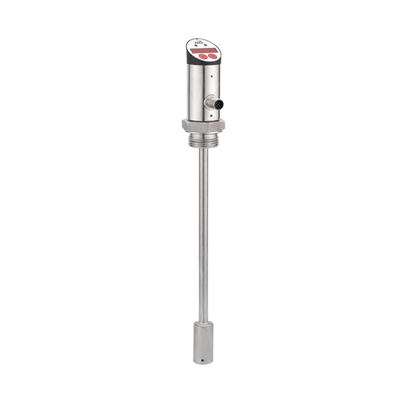
The capacitive level sensor consists of two electrodes: the sensing probe (one plate of the capacitor) and either the vessel wall or a separate reference electrode (the other plate). The medium between them acts as the dielectric.
As material level rises, more of the probe is surrounded by the process medium rather than air. Since the medium has a higher dielectric constant than air, total capacitance increases. The sensor's electronics — typically an oscillator circuit — detect this capacitance change, linearize it against the known dielectric properties of the medium, and output a 4–20 mA analog signal proportional to level, or activate a discrete switching output at a set point.
Insulated vs. Bare Probes
Capacitive probes are available in two configurations. Bare metal probes are used in non-conductive media such as oils, fuels, and dry bulk solids — the medium itself forms the dielectric. Insulated probes, coated with PTFE, polyethylene, or ceramic, are used in conductive liquids such as water, acids, and alkalis. The insulating layer prevents the conductive liquid from short-circuiting the sensor while still allowing the capacitance measurement to function correctly through the coating's own dielectric properties.
Active Shielding and Buildup Compensation
Modern capacitive sensors incorporate active shielding — a guard electrode driven at the same potential as the sensing electrode — to eliminate stray capacitance from the vessel wall and wiring. Advanced models also include automatic buildup compensation: electronics that continuously monitor the capacitance of material adhering to the probe tip and subtract this offset from the measurement, preventing false readings caused by sticky or coating media.
Non-Contact Level Sensing Technologies Explained
Ultrasonic Level Sensors
Ultrasonic sensors emit short pulses of high-frequency sound (typically 40–200 kHz) from a transducer mounted above the vessel. The pulse reflects off the material surface and returns to the transducer; the elapsed time is measured and converted to distance. Ultrasonic sensors are the most cost-effective non-contact option for standard water, wastewater, and bulk solid applications. Their key limitation is sensitivity to vapor, foam, turbulence, and extreme temperatures — all of which can absorb or scatter the sound pulse and cause signal loss.
Radar (Microwave) Level Sensors
Radar level sensors operate on the same time-of-flight principle but use microwave signals (typically 6, 26, or 80 GHz) instead of sound. Microwaves are unaffected by vapor, dust, foam, temperature extremes, and most atmospheric conditions that defeat ultrasonic measurement. 80 GHz radar sensors represent the current industry standard for demanding applications: their narrow beam angle (as small as 3 degrees) allows installation in vessels with internal obstructions such as agitators, heating coils, and nozzles without signal interference. Radar sensors can measure levels in tanks up to 70 meters deep with accuracy to within ±1 mm in optimal conditions.
Laser Level Sensors
Laser-based non-contact sensors use pulsed infrared or visible light to measure distance to a material surface. They offer the narrowest beam of any non-contact technology — typically less than 1 degree — making them ideal for measuring through small vessel openings or profiling uneven solid surfaces. Laser sensors are less suited to dusty environments where the beam may be attenuated before reaching the surface, and they are generally more expensive than radar alternatives for equivalent performance.

Industrial Applications: Where Each Technology Excels
Both capacitive and non-contact level sensors are deployed across virtually every process industry. Understanding where each technology performs best prevents costly misapplication.
- Food and Beverage: Non-contact radar and ultrasonic sensors dominate in hygienic applications — measuring levels in ingredient silos, mixing tanks, and clean-in-place vessels where sensor contact would create contamination risks or require expensive sanitary probe designs. Capacitive sensors with hygienic flush-mount fittings are used for point-level detection in tanks requiring CIP certification.
- Chemical Processing: Non-contact radar sensors handle corrosive acids, alkalis, and solvents that would attack probe materials. Capacitive sensors with PTFE-coated probes and chemically resistant housings cover conductive aggressive liquids where vessel geometry precludes top-mounted non-contact installation.
- Oil and Gas: Radar sensors are standard for custody-transfer tank gauging, where measurement accuracy directly affects financial transactions. Capacitive sensors provide reliable interface detection — identifying the boundary between oil and water layers in separator vessels.
- Water and Wastewater: Ultrasonic non-contact sensors are widely used in open channels, sumps, and reservoirs for level monitoring and flow measurement. Capacitive sensors provide reliable pump control switching in wet wells and lift stations.
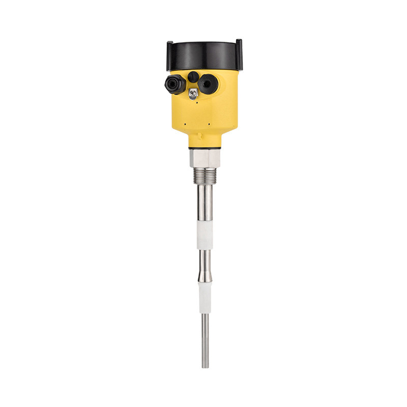
- Bulk Solids and Silos: Non-contact radar sensors handle dust, bridging, and uneven surface profiles in grain silos, cement hoppers, and plastic pellet storage. Capacitive sensors with extended rod or cable probes are used for point-level high/low alarms in the same vessels.
- Pharmaceuticals: Both technologies are applied in pharmaceutical manufacturing, with non-contact sensors preferred in sterile vessels. Capacitive sensors with electropolished stainless probes and FDA-compliant materials serve point-level detection in buffer and reagent tanks.
Installation and Commissioning Considerations
Correct installation is as important as sensor selection in achieving reliable level measurement. Several installation factors directly affect performance for both technologies.
Capacitive Sensor Installation
Capacitive probes should be mounted away from vessel walls, agitators, and inlet/outlet nozzles to avoid false readings from turbulence or proximity effects. The minimum recommended clearance from the vessel wall is typically 100–150 mm, though this varies by probe diameter and vessel geometry. For conductive vessels, the probe's reference electrode function is provided by the vessel wall — for non-conductive vessels such as plastic tanks, a separate ground reference probe or coaxial probe design is required. Calibration involves recording the empty and full capacitance values, allowing the electronics to linearize the output across the measurement span.
Non-Contact Sensor Installation
Non-contact sensors must be mounted so the transmitted beam travels in a clear path to the material surface without striking vessel walls, internal fittings, or fill streams. The sensor should be positioned off-center in round vessels to avoid false echoes from the opposite curved wall. A minimum distance — the blocking distance — must be maintained between the sensor face and the maximum fill level; no measurement is possible within this near-range zone. For ultrasonic sensors, the blocking distance is typically 150–500 mm; for radar sensors, it is as small as 50 mm in modern 80 GHz units. After installation, both technologies require a mapping routine that records and suppresses fixed false echoes from internal vessel structures.
Output Signals, Communication Protocols, and Integration
Modern capacitive and non-contact level sensors are available with a range of output and communication options to suit different control system architectures.
The 4–20 mA analog signal remains the industrial standard for continuous level transmitters, offering inherent noise immunity and the ability to detect sensor faults through out-of-range current values. HART protocol superimposed on the 4–20 mA loop allows digital communication of diagnostic data, secondary variables, and configuration parameters without additional wiring. For installations requiring fieldbus integration, PROFIBUS PA, Foundation Fieldnet, and IO-Link variants are available across most major sensor families.
Wireless variants using WirelessHART or ISA100.11a protocols are increasingly deployed for remote or difficult-to-access vessels where cable installation is impractical. Battery-powered wireless level sensors with operational lives of five to ten years are now available from multiple manufacturers, making them viable for permanent installation in locations previously served only by manual gauging.
Selecting Between Capacitive and Non-Contact Technologies: A Practical Decision Guide
For engineers and procurement specialists evaluating level measurement options, the following decision framework simplifies technology selection.
Choose a capacitive level sensor when the process medium has a sufficiently high and stable dielectric constant (greater than approximately 1.5 for reliable measurement), when the vessel geometry requires a probe-type installation, when point-level switching is the primary requirement, or when budget constraints favor the lower initial cost of capacitive technology over radar alternatives.
Choose a non-contact level sensor when the process medium is corrosive, toxic, or at extreme temperature or pressure such that wetted components are undesirable, when hygienic requirements prohibit probe contact, when the medium coats or builds up on surfaces in a way that would foul a probe, or when the measurement range exceeds practical probe lengths. Radar is the preferred non-contact technology in most industrial applications due to its immunity to process vapors and foam — reserve ultrasonic for straightforward, clean-medium applications where cost is the primary driver.
In many facilities, both technologies coexist — capacitive sensors providing reliable point-level alarms and pump control at low cost, while non-contact radar transmitters deliver continuous inventory measurement in the same vessels. This layered approach combines the strengths of each technology to maximize both reliability and cost efficiency.
information
 [email protected]
![]() +86-13386111894 / +86-021-37566990
+86-13386111894 / +86-021-37566990
![]() B-4th Floor, Lane 1313, Nanting Road, Nanqiao Town, Fengxian District, Shanghai, China
B-4th Floor, Lane 1313, Nanting Road, Nanqiao Town, Fengxian District, Shanghai, China

Product Links