 en
en English
 Русский
 España
 عرب .
عرب .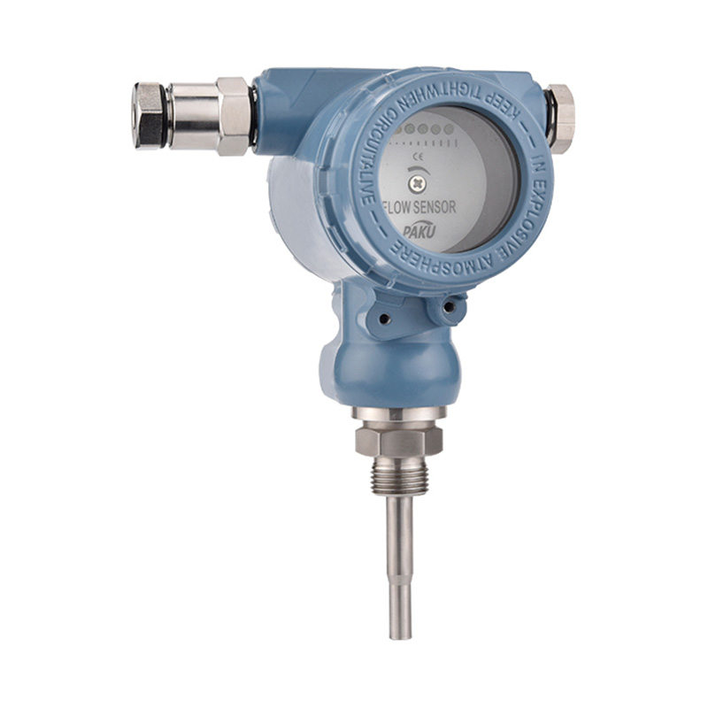

If you need any help, please feel free to contact us
inquire
If you have any further questions, please call +86-021-37566990 or fill out the inquiry form.
Get coupons PDF DownloadPointer Flow Switch-SN510
Product introduction
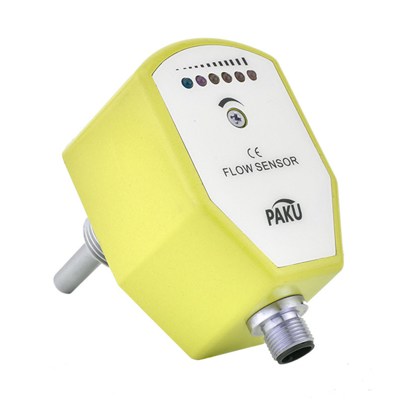
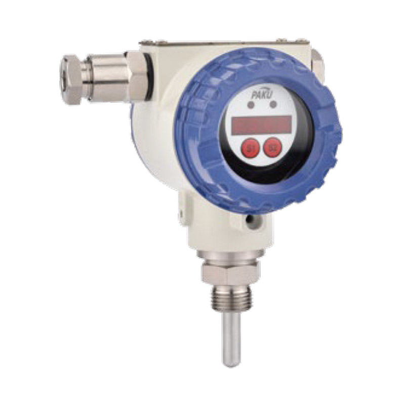
SN510 series pointer flow switch is mainly used for liquid flow monitoring and switching output in pipelines.
Its solid structure and stable performance can be widely used in the cooling and lubrication systems of generators, motors, rolling mills, compressors, conveyors and other machines. It can output a control signal when the flow rate exceeds or falls below a preset switching point. This preset switch point can be set at any position in the range, and the switch point can be easily adjusted under post-installation conditions.
-Streamlined design, robustness and durability.
-Magnetic coupling measurement system.
-Installation direction is arbitrary; vertical and horizontal installation is arbitrary.
-Multiple material options. Wide measuring range.
-Clear flow rate display scale, easy to read, rotating pointer.
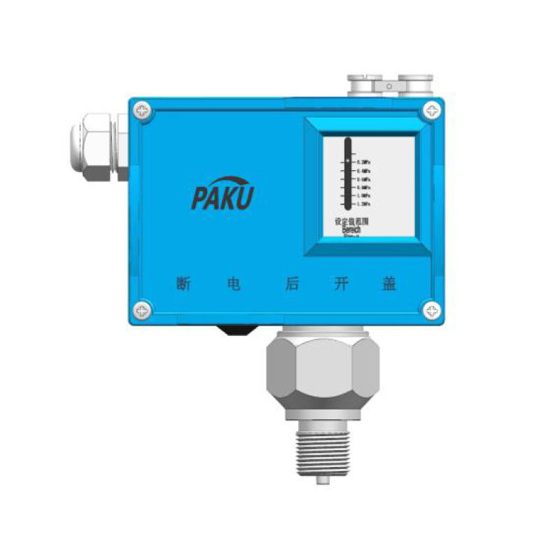
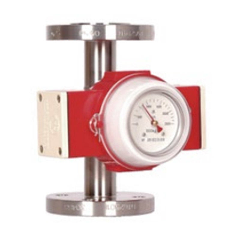
Model SN510-A
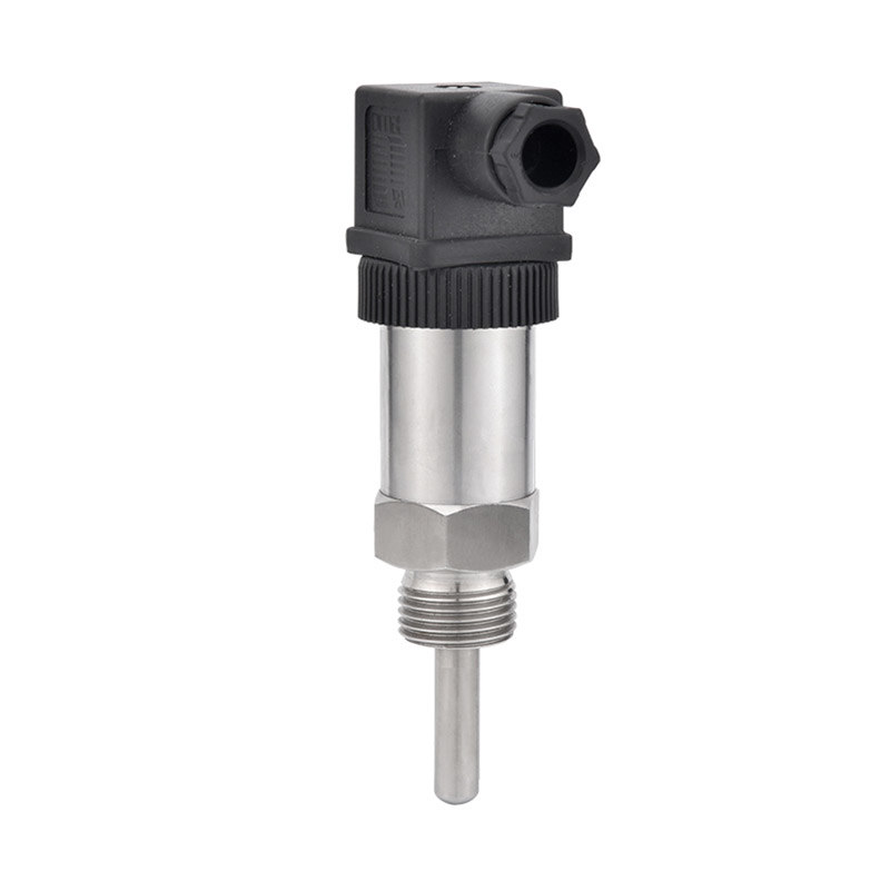
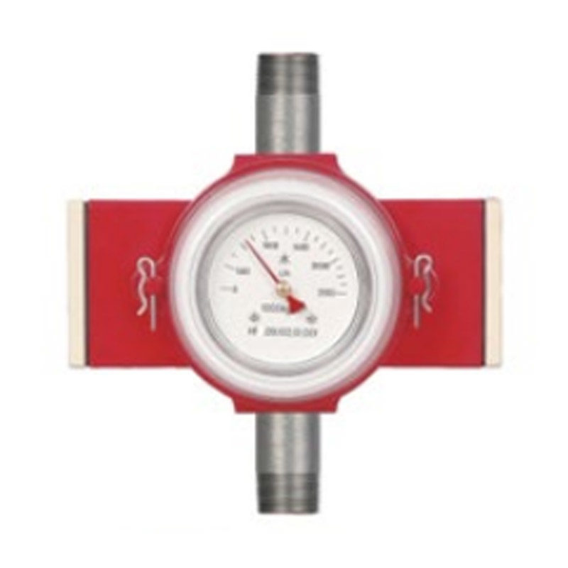
Model SN510-B
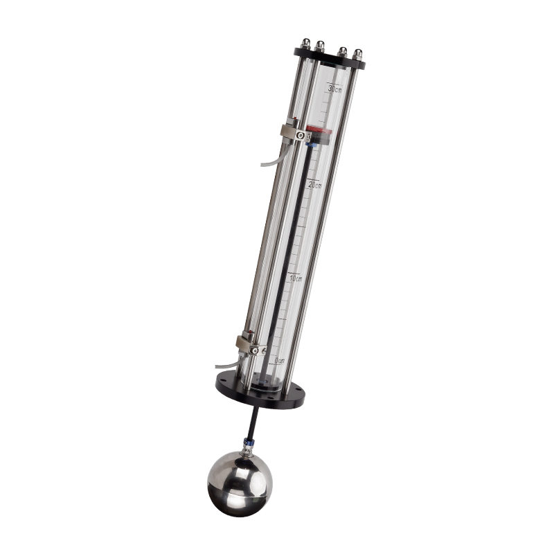
Model SN510-B
Range Chart
Pointer Form
Technical Parameters
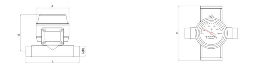
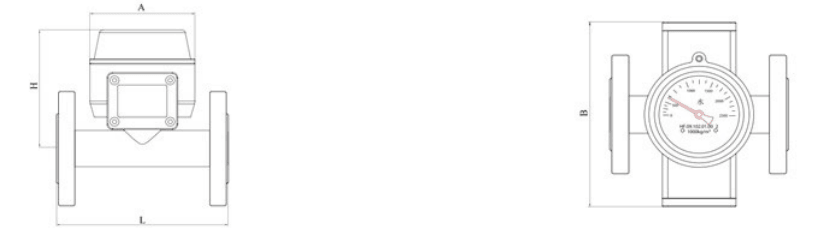
Overall Dimensions
SN510-A
Installation And Use
Commissioning And Flow Switch Point Adjustment
Maintenance and General Troubleshooting
Selection Table
-Pipe thread connection 3/4"~21/2’
-Suitable for horizontal and vertical pipes
-Rotating form scale
-1 or 2 flow limit switches
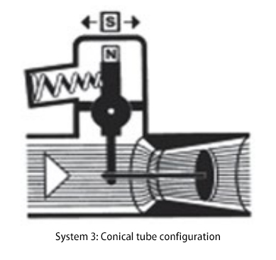
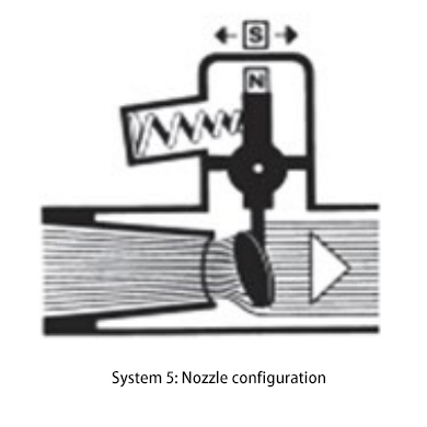
-Measuring system 3 or 5
-Flange connection DN15~DN50/65 (1/2‘~21/2’)
-Applicable to horizontal and vertical pipelines
-Rotary form scale
-1 or 2 flow limit switches
-Measuring system 3 or 5
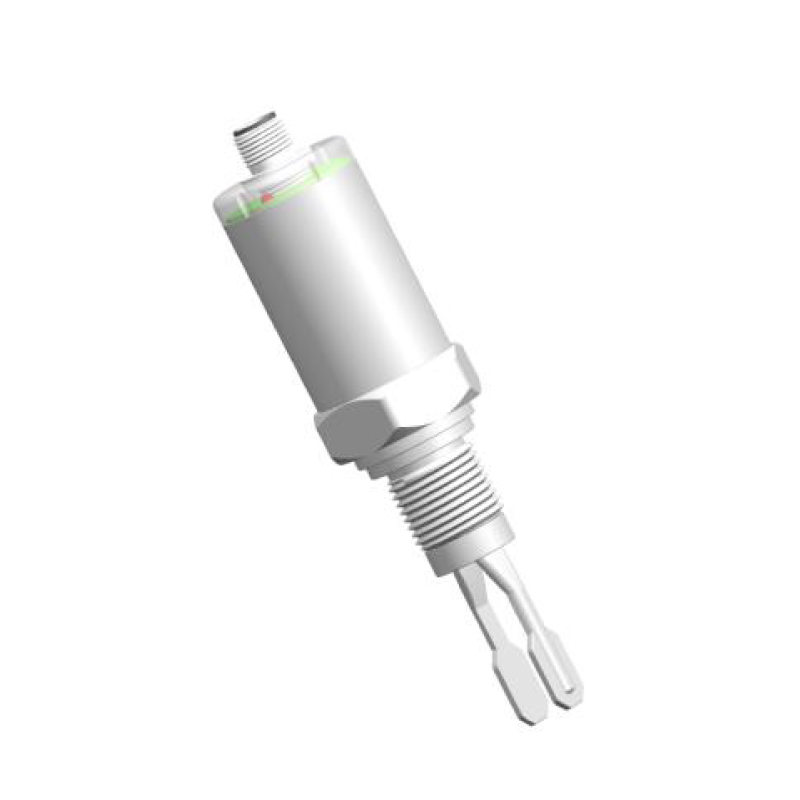
-Flange connection DN80~DN200(3‘~8’)
-Applicable to horizontal and vertical pipelines
-Rotary form scale
-1 or 2 flow limit switches
-Measuring system 7
Adopting conical measuring tube and measuring target, when the fluid passes along the conical tube, the measuring target generates displacement according to the size of the flow rate, the displacement of the measuring target is balanced by the action of spring balancing force, which is transmitted to the indication system through the magnetic coupling system to realise the monitoring and control of the flow rate.
| SN510-A | SN510-B | Flow range L/H | No. | Pressure loss | ||||||||||||||||||||||||
| 3/4” | DN15 | 20-160 | 1501 | 8.5 | ||||||||||||||||||||||||
| 40-250 | 1502 | 12.0 | ||||||||||||||||||||||||||
| 50-400 | 1503 | 15.0 | ||||||||||||||||||||||||||
| 80-600 | 1504 | 20.0 | ||||||||||||||||||||||||||
| 50-1000 | 1505 | 45.0 | ||||||||||||||||||||||||||
| 200-1600 | 1506 | 45.0 | ||||||||||||||||||||||||||
| 300-2500 | 1507 | 45.0 | ||||||||||||||||||||||||||
| 1” | DN25 | 200-1600 | 2501 | 10.0 | ||||||||||||||||||||||||
| 300-2500 | 2502 | 20.0 | ||||||||||||||||||||||||||
| 400-3000 | 2503 | 30.0 | ||||||||||||||||||||||||||
| 500-4000 | 2504 | 40.0 | ||||||||||||||||||||||||||
| 1-1/2” | DN40 | 500-4000 | 4001 | 7.0 | ||||||||||||||||||||||||
| 800-6000 | 4002 | 11.0 | ||||||||||||||||||||||||||
| 1000-8000 | 4003 | 13.0 | ||||||||||||||||||||||||||
| 1200-10000 | 4004 | 15.0 | ||||||||||||||||||||||||||
| 2”(2-1/2”) | DN50(65) | 1200-10000 | 5001 | 8.0 | ||||||||||||||||||||||||
| 2000-16000 | 5002 | 25.0 | ||||||||||||||||||||||||||
| 2500-20000 | 5003 | 35.0 | ||||||||||||||||||||||||||
| 4000-25000 | 5004 | 38.0 | ||||||||||||||||||||||||||
| 7500-30000 | 5005 | 40.0 | ||||||||||||||||||||||||||
| SN510-C | Flow range m³/H | No. | Pressure loss | |||||||||||||||||||||||||
| DN80 | 10-40 | 8001 | 1.5 | |||||||||||||||||||||||||
| 12-50 | 8002 | 1.0 | ||||||||||||||||||||||||||
| 16-60 | 8003 | 1.0 | ||||||||||||||||||||||||||
| 20-70 | 8004 | 1.0 | ||||||||||||||||||||||||||
| DN100 | 15-60 | 10001 | 2.0 | |||||||||||||||||||||||||
| 20-80 | 10002 | 1.5 | ||||||||||||||||||||||||||
| 25-100 | 10003 | 2.0 | ||||||||||||||||||||||||||
| 30-120 | 10004 | 3.0 | ||||||||||||||||||||||||||
| DN125 | 25-100 | 12501 | 2.5 | |||||||||||||||||||||||||
| 30-120 | 12502 | 2.5 | ||||||||||||||||||||||||||
| 40-150 | 12503 | 2.5 | ||||||||||||||||||||||||||
| 45-180 | 12504 | 3.0 | ||||||||||||||||||||||||||
| DN150 | 40-150 | 15001 | 3.0 | |||||||||||||||||||||||||
| 45-180 | 15002 | 3.5 | ||||||||||||||||||||||||||
| 60-220 | 15003 | 3.5 | ||||||||||||||||||||||||||
| 65-250 | 15004 | 3.0 | ||||||||||||||||||||||||||
| DN200 | 50-220 | 20001 | 4.5 | |||||||||||||||||||||||||
| 70-250 | 20001 | 4.0 | ||||||||||||||||||||||||||
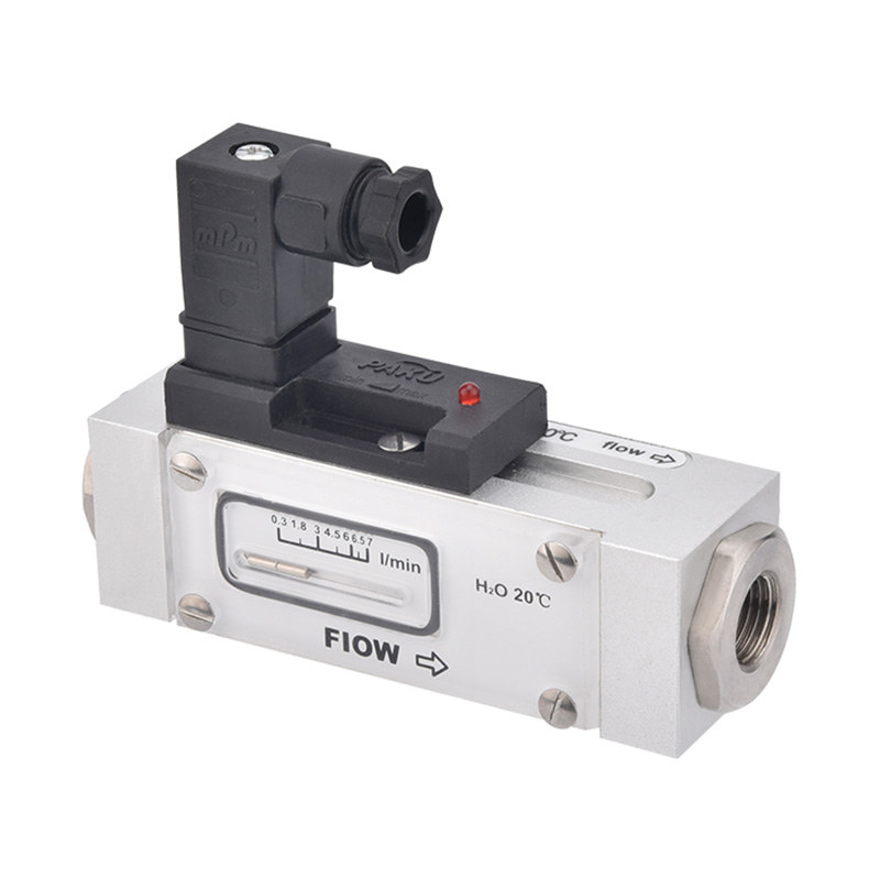
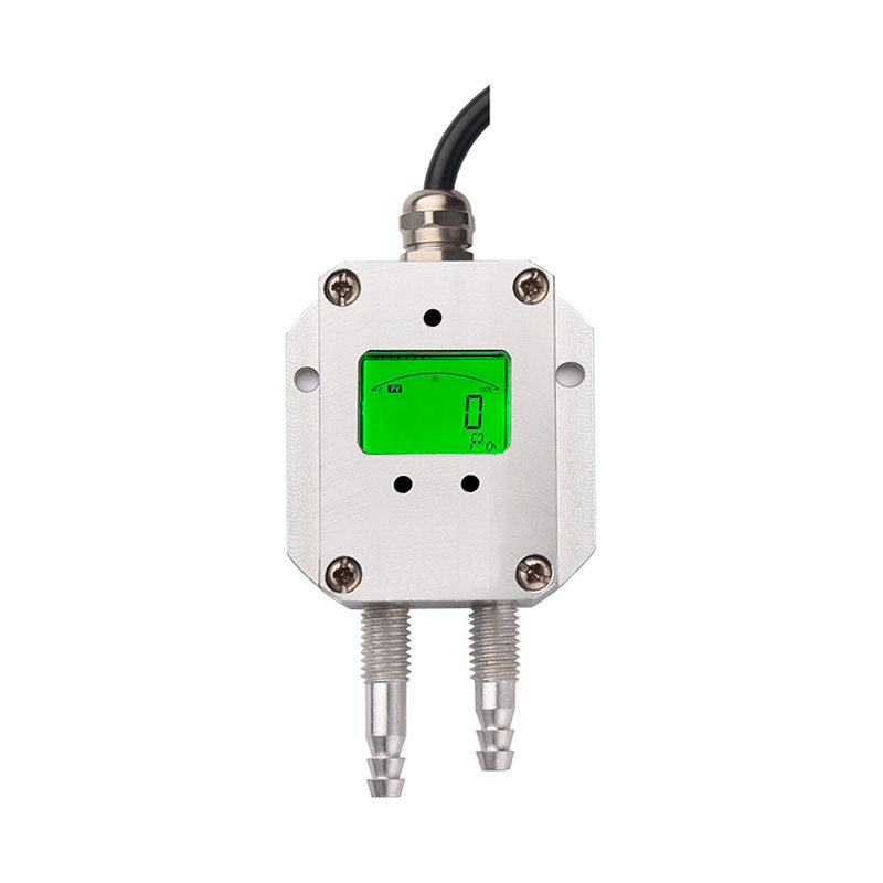
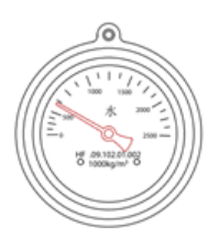
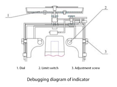
Indicator for flow switches (see figure on the right).
The corresponding measuring ranges are divided into L/h, L/min and m²/h dials, and the circular dial and rotating pointer allow easy observation of the flow rate.
The most important feature of the indicator is that the switching alarm point can be easily adjusted without interrupting the flow in the pipeline.
| Model | SN510-A | SN510-B | SN510-C |
| Body | 304/316 | 304/316 | 304/316 |
| Transmission | 304/316 | 304/316 | 304/316 |
| Measuring system | 304/316 | 304/316 | 304/316 |
| Gaskets | PTFE | PTFE | PTFE |
| Meter housing | plastics | plastics | plastics |
| Instrument Model | SN510-A | SN510-B | SN510-C | |||||||||||||||||||||||||
| Measuring range | Flow rate (m³/h) | 0.02-30 | 0.02-30 | 10-250 | ||||||||||||||||||||||||
| Connection form | Threaded connection | 3/4 ”-2 1/2 ” | - | - | ||||||||||||||||||||||||
| Flange connection | - | DN15-DN65 | DN80-DN200 | |||||||||||||||||||||||||
| Special forms | According to the user's requirements | According to the user's requirements | According to the user's requirements | |||||||||||||||||||||||||
| Measuring system | Target plate Nozzle | 5 | 5 | 7 | ||||||||||||||||||||||||
| Target plate Tapered tube | 3 | 3 | 7 | |||||||||||||||||||||||||
| Indicator | Rotary scale | Flow Rate Field Indication | Flow Rate Field Indication | Flow Rate Field Indication | ||||||||||||||||||||||||
| Fluid direction | Vertical | C | C | C | ||||||||||||||||||||||||
| Horizontal | S | S | S | |||||||||||||||||||||||||
| Arbitrary direction | According to the user's requirements | According to the user's requirements | According to the user's requirements | |||||||||||||||||||||||||
| Maximum operating pressure | Threaded connection | 4.0MPa | - | - | ||||||||||||||||||||||||
| Flange connection | - | 4.0MPa | 1.6MPa | |||||||||||||||||||||||||
| Special forms | According to the user's requirements | According to the user's requirements | According to the user's requirements | |||||||||||||||||||||||||
| Medium temperature | Standard type | ≤120 | ≤120 | ≤120 | ||||||||||||||||||||||||
| Special type | According to the user's requirements | According to the user's requirements | According to the user's requirements | |||||||||||||||||||||||||
| Viscosity of the medium mpa.s |
Standard type | ≤30 | ≤30 | ≤30 | ||||||||||||||||||||||||
| Special type | According to the user's requirements | According to the user's requirements | According to the user's requirements | |||||||||||||||||||||||||
| Switching Repeatability | ±2.5% | ±2.5% | ±2.5% | |||||||||||||||||||||||||
| Measurement accuracy | ±8% 、 ± 12% | ±8% 、 ± 12% | ±8% 、 ± 12% | |||||||||||||||||||||||||
| Alarm switch | K1 | 1 NC or 1 NO contact (bistable) | ||||||||||||||||||||||||||
| K2 | 2 NC or 2 NO contacts (bistable) | |||||||||||||||||||||||||||
| KV1 | 1 switching contact of amplifying relay (bistable) | |||||||||||||||||||||||||||
| KV2 | 2 switching contacts of amplifying relay (bistable) | |||||||||||||||||||||||||||
| Contact power | K1,K2 | Maximum 12VA (Maximum: 220VAC/Maximum: 0.5A), 24VDC power supply is recommended. | ||||||||||||||||||||||||||
| KV1 KV2 |
Contact power | Maximum 1200VA (Maximum: 250VAC/Maximum: 5A) | ||||||||||||||||||||||||||
| Power supply | 220VAC,24VDC | |||||||||||||||||||||||||||
| Corresponding time | 5-12ms | |||||||||||||||||||||||||||
| protection class | IP65 | |||||||||||||||||||||||||||
| Model | Connection | A | B | L | H | weights(kg) | ||||||||||||||||||||||
| SN510-A | G( R)3/4 ” | Φ 103 | 180 | 135 | 120 | 2.0 | ||||||||||||||||||||||
| G( R) 1 ” | Φ 103 | 180 | 160 | 120 | 2.0 | |||||||||||||||||||||||
| G( R) 1 1/2 ” | Φ 103 | 180 | 180 | 130 | 3.0 | |||||||||||||||||||||||
| G( R)2 ” ( 2 1/2 ”) |
Φ 103 | 180 | 180 | 130 | 3.0 | |||||||||||||||||||||||
| SN510-B | DN15 | Φ 103 | 180 | 200 | 120 | 3.0 | ||||||||||||||||||||||
| DN25 | Φ 103 | 180 | 200 | 130 | 4.0 | |||||||||||||||||||||||
| DN40 | Φ 103 | 180 | 200 | 130 | 6.0 | |||||||||||||||||||||||
| DN50 | Φ 103 | 180 | 200 | 140 | 7.5 | |||||||||||||||||||||||
| DN65 | Φ 103 | 180 | 200 | 140 | 10.0 | |||||||||||||||||||||||
| SN510-C | DN80 | Φ 103 | 180 | 200 | 190 | 13.0 | ||||||||||||||||||||||
| DN100 | Φ 103 | 180 | 200 | 200 | 15.0 | |||||||||||||||||||||||
| DN125 | Φ 103 | 180 | 300 | 210 | 20.0 | |||||||||||||||||||||||
| DN150 | Φ 103 | 180 | 300 | 220 | 25.0 | |||||||||||||||||||||||
| DN200 | Φ 103 | 180 | 300 | 250 | 35.0 | |||||||||||||||||||||||
1. The flow switch should first be cleaned of impurities, welding slag, debris, and dirty items in the pipeline before installation, and compressed air blowing and clean water flushing are recommended.
2. Please pay attention to the fluid flow direction marked on the instrument case, the arrow is the outflow direction.
3. It is recommended to install a straight pipe section equivalent to 5 times of the calibre at the inlet and outlet to ensure the measurement accuracy.
1. The flow switch has been debugged and calibrated at the manufacturer's factory before leaving the factory, and has been inspected and qualified by a full-time inspector.
2. When using the flow switch for the first time or in the future; please open the inlet valve gently and slowly to avoid damaging the flow switch.
3. The switching point of the flow switch can be adjusted in the full flow range, which can be adjusted without cutting off the water flow.
4. Indicator commissioning: open the shell, according to the desired flow value alarm point, keep the flow at the flow point, then loosen the adjusting screws with a tool, carefully adjust the alarm
switch position, so that the alarm switch in the flow point to produce action.
5. After adjusting the alarm switch, tighten the adjusting screws, and finally tighten the instrument case.
Under normal conditions, the flow switch can be free of maintenance and repair. If there are impurities, granular substances or suspended matter in the fluid, it will block the measuring body of the flow switch, and the above phenomena should be removed and cleaned in time.
The above phenomena should be removed and cleaned up in time, and then in the process of cleaning up, you should be careful not to damage the internal parts of the flow switch, in order to ensure the normal operation of the flow switch.
In case of malfunction that cannot be handled on site, please do not dismantle it easily. It is recommended that you send the flow switch back to the manufacturer for inspection and repair. Please follow the following procedure
On-site processing.
1. Measurement without indication; first check whether there are impurities, granular substances or suspended matters that may block the measuring body of the flow switch, remove the impurities and return to normal.
2. The flow rate is sometimes there, sometimes not; first check whether there is damage to the measuring element, if there is damage, please contact with the manufacturer.
3. Measurement inaccuracy; first check whether the flute element is damaged, if there is damage, please contact with the manufacturer.
4. Leakage occurs; first check whether the seal is intact, the biggest possibility is that the O-ring of the seal is damaged, please replace it in time.
| SN510- | A | R4 | 3 | 1 | H | K1 | S | A | Detailed Description |
| SN510- | Pointer Flow Switch | ||||||||
| Classification Model | A | External thread - pipe thread mounting (3/4‘-21/2’) | |||||||
| B | Flange mounting (DN15-DN65) | ||||||||
| C | Flange mounting (DN80-DN200) | ||||||||
| Material | R4 | 304 Stainless Steel | |||||||
| R6 | 316 Stainless Steel | ||||||||
| Special materials | |||||||||
| Flow classification | 3 | Cone pipe form | |||||||
| 5 | Nozzle form | ||||||||
| Display form | 1 | Indicator a rotary form scale | |||||||
| Case temperature | H | Maximum temperature 120℃ (standard type) | |||||||
| HO | Max. temperature 200°C (with heat sink housing) | ||||||||
| Alarm switch | K1 | 1 NC or 1 NO contact (bistable) | |||||||
| K2 | 2 NC or 2 NO contacts (bistable) | ||||||||
| KV1 | 1 switching contact of amplifying relay (bistable) | ||||||||
| KV2 | 2 switching contacts of amplifying relay (bistable) | ||||||||
| Installation form | S | Horizontal mounting | |||||||
| C | Vertical mounting | ||||||||
| Customised models, on request | |||||||||
| Explosion-proof type | A | Non-explosion-proof | |||||||
| B | Ex-proof | ||||||||
Shanghai Kayuan Electronic
Technology Co., Ltd.
Technology Co., Ltd.
Shanghai Kayuan Electronic Technology Co.,Ltd is an enterprise specializing in the production and R & D of industrial sensors and controllers. Its main products include switches and sensors for flow, pressure, temperature, and liquid level. Pointer Flow Switch-SN510 Suppliers in China.
In 2008, our assembly plant was established in Shanghai China,PAKU INTELLIGENT EQUIPMENT(SHANGHAI)CO.,LTD a subsidiary of Kayuan to produce the PAKU series of products. As Pointer Flow Switch-SN510 Factory, PAKU products are now widely used in different industries, including automation complete sets of equipment, petroleum equipment, chemical equipment, power equipment, welding equipment, steel equipment, metallurgical equipment, automobiles, and water treatment. We adopt advanced technology and manufacturing processes across the board. With our professional design and production technology, comprehensive product lines, excellent quality, and sales network services, we can not only provide users with timely and professional technical support but also offer high - quality one - stop services.
We have served many customers at home and abroad, and offer Pointer Flow Switch-SN510 Wholesale, our products are sold to countries such as Canada, the United States, Brazil, Indonesia, Vietnam, Thailand, and Russia. We welcome extensive cooperation with OEM and ODM customers.

information
 [email protected]
![]() +86-13386111894 / +86-021-37566990
+86-13386111894 / +86-021-37566990
![]() B-4th Floor, Lane 1313, Nanting Road, Nanqiao Town, Fengxian District, Shanghai, China
B-4th Floor, Lane 1313, Nanting Road, Nanqiao Town, Fengxian District, Shanghai, China

Product Links