If you need any help, please feel free to contact us
Electronic Flow Switches: Ensuring Efficient and Reliable Fluid Control
In the intricate networks of pipes and conduits that power our modern world—from sprawling industrial plants to the climate control systems in office buildings—the precise management of fluid flow is paramount. Ensuring that water, chemicals, air, and other media are moving at the correct rate is not just a matter of efficiency; it is a critical factor in safety, equipment protection, and process integrity. At the heart of this crucial task lies a sophisticated device: the electronic flow switch.
1. Introduction
1.1 Definition of Electronic Flow Switches
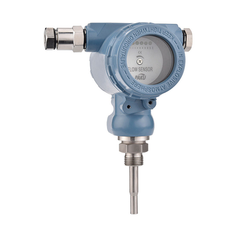
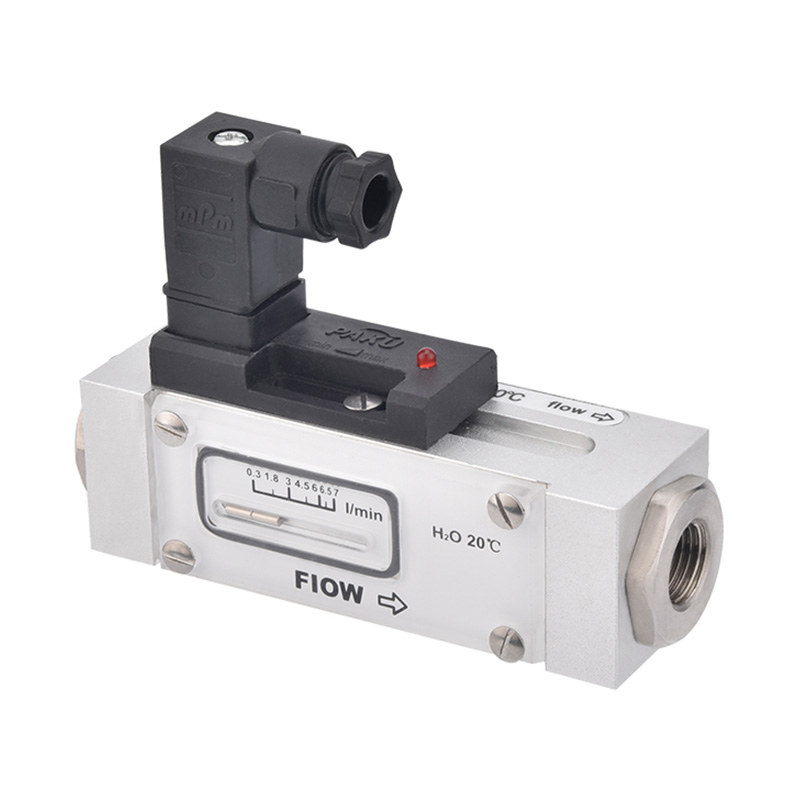
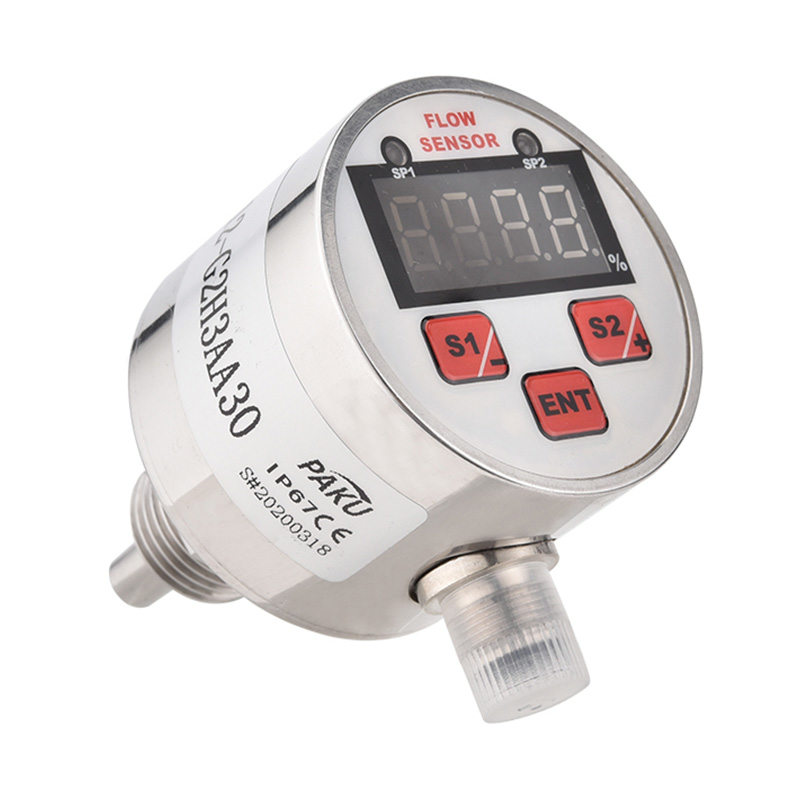
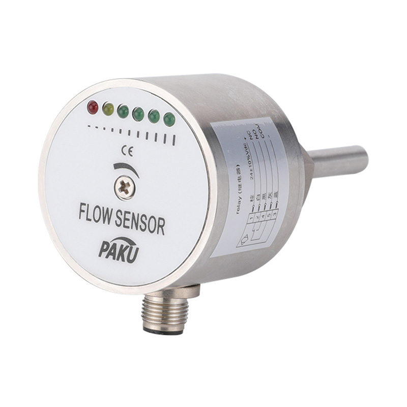
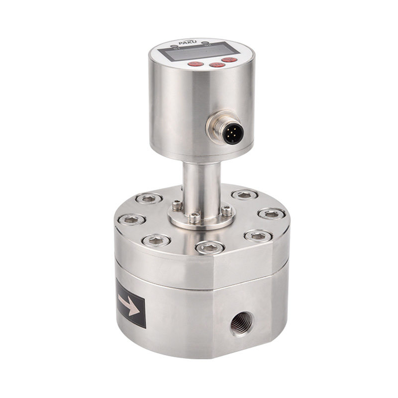
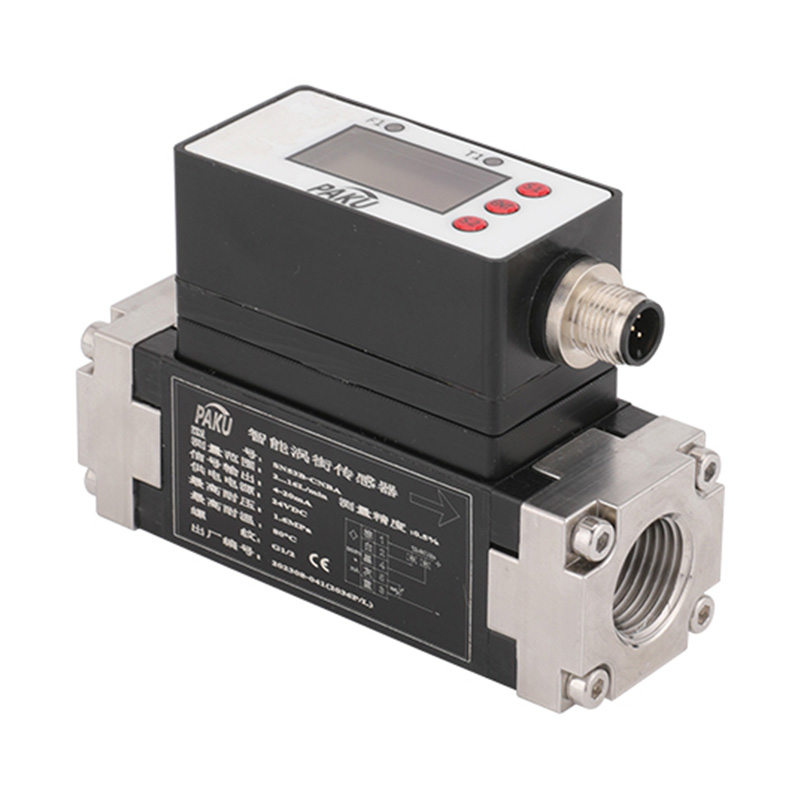
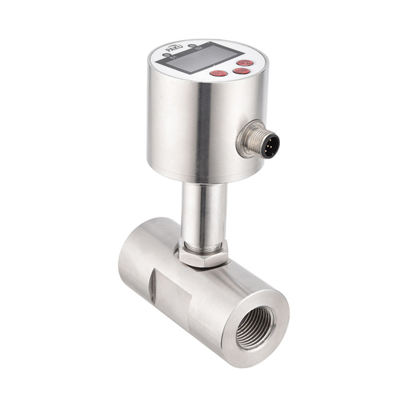
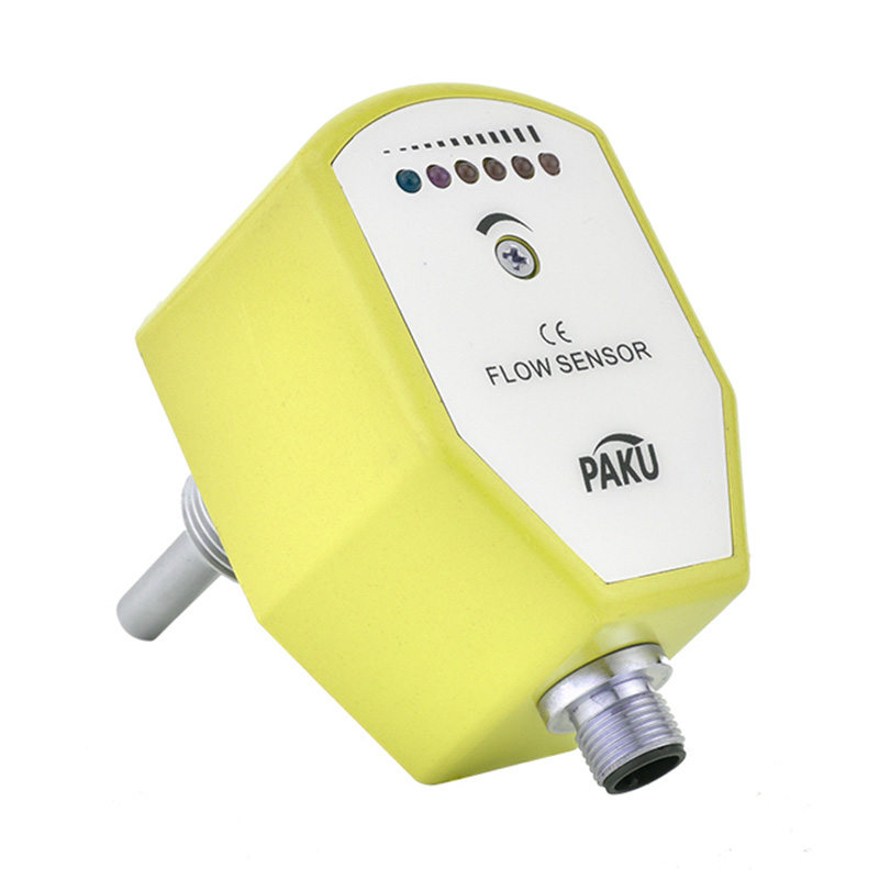
An electronic flow switch is an advanced monitoring device designed to detect the presence, absence, or rate of flow of a liquid or gas within a pipe or duct. Unlike traditional mechanical flow switches that use a paddle or piston activated by the fluid to trigger a simple electrical switch, electronic variants employ solid-state sensors to measure flow phenomena directly. They then generate an electronic signal that can be used for monitoring, alarm triggers, or automatic control functions within a larger system.
1.2 Importance in Industrial and Commercial Fluid Systems
The reliability of fluid systems is non-negotiable. A loss of coolant flow can lead to catastrophic equipment failure in a manufacturing plant. An imbalance in a heating system can cause comfort issues and energy waste in a commercial building. Electronic flow switches serve as the sentinels of these systems, providing continuous, real-time data that ensures processes operate within their designed parameters. They are fundamental to automation, allowing for immediate corrective actions without human intervention, thereby enhancing safety, optimizing performance, and preventing costly downtime.
1.3 Overview of Applications and Benefits
The versatility of electronic flow switches allows them to be deployed across a vast spectrum of applications. They are found safeguarding pumps from running dry, verifying filter function, ensuring proper lubrication to machinery, and controlling chemical dosing rates. The primary benefits they offer include a significant improvement in system efficiency, superior protection for valuable assets, the ability to monitor performance remotely, and a reduction in maintenance needs compared to their mechanical counterparts.
By providing a critical link between the physical movement of fluid and digital control systems, electronic flow switches are indispensable components in the pursuit of smarter, safer, and more efficient fluid management.
2. How Electronic Flow Switches Work
Understanding the inner workings of electronic flow switches is key to appreciating their advantages. They replace moving mechanical parts with sophisticated sensors and electronics, leading to greater reliability and more detailed data.
2.1 Basic Operating Principles
At their core, electronic flow switches operate on a simple two-stage principle: sensing and signaling. First, a sensor element continuously measures a specific physical property of the fluid that is directly related to its flow rate. This sensor does not obstruct the flow path. Second, the device’s internal electronics (a microprocessor) interpret this sensor reading. It compares the measured value to one or more user-defined setpoints. If the flow rate rises above or falls below this preset threshold, the electronics trigger a change in its output signal to alert the control system of the condition.
2.2 Types of Sensing Technologies
Different applications demand different measurement techniques. Electronic flow switches primarily use three types of non-invasive or minimally invasive sensing technologies:
- Thermal (Thermal Dispersion): This common technology uses two temperature sensors: one heated and one that measures the ambient fluid temperature. The flow rate is determined by calculating the amount of heat lost from the heated sensor to the flowing fluid. A faster flow carries away more heat, creating a greater temperature difference between the two sensors. These switches are excellent for detecting very low flow rates of clean gases and liquids.
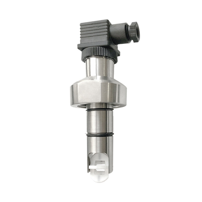
- Magnetic (Paddle or Vane): While some use a physical paddle in the stream, more advanced electronic versions use a magnet attached to a paddle. As flow moves the paddle, the magnet’s movement is detected by a sealed, non-contact Hall Effect sensor. This combines the simplicity of a mechanical trigger with the reliability of electronic sensing, making it robust for a wide range of liquid applications.
- Ultrasonic: This non-intrusive technology works by transmitting an ultrasonic signal diagonally across the pipe. The transit time of the signal is measured both with and against the flow. The flow rate of the fluid causes a difference in these transit times (time difference or “transit-time” method), which the device calculates to determine velocity. This method is ideal for applications where no contact with the fluid is desired, such as with corrosive or ultra-pure liquids.
2.3 Signal Output and Integration with Control Systems
This is where electronic flow switches truly shine over mechanical ones. Instead of a simple on/off switch, they provide versatile electronic outputs that can be easily integrated into modern control architectures. Common outputs include:
- Analog Signals (e.g., 4-20 mA or 0-10 VDC): These provide a continuous, proportional signal that represents the actual flow rate. A 4 mA output might signify no flow, 12 mA half-scale flow, and 20 mA full-scale flow. This allows for continuous monitoring and data logging on a SCADA system or PLC.
- Digital Signals (e.g., Relay Switch): Like a mechanical switch, a relay output provides a simple on/off signal based on the setpoint. However, it is triggered electronically, not mechanically, leading to a longer lifespan and no risk of contact chatter.
- Networked Communication (e.g., IO-Link, Modbus, HART): Advanced “smart” switches can communicate digitally, providing not just flow rate and alarm status but also device health diagnostics, temperature data, and configuration details directly to a controller.
This seamless integration allows a building management system to alert a technician to a clogged filter in real-time or enables a programmable logic controller (PLC) to automatically shut down a pump if coolant flow is lost, preventing catastrophic failure.
3. Key Features and Specifications
Selecting the right electronic flow switch requires a careful examination of its specifications. These technical parameters ensure the device will perform accurately, reliably, and safely within a specific system. Understanding these key features is crucial for making an informed decision.
3.1 Flow Rate Range and Response Time
- Flow Rate Range: This defines the minimum and maximum flow rates the switch can accurately measure and monitor. It is typically expressed in units like gallons per minute (GPM), liters per minute (L/min), or feet per second (m/s). Choosing a switch whose operating range comfortably encompasses your system’s expected flow rates is essential. A range that is too large can sacrifice accuracy at lower flows, while one that is too small may not function or could be damaged.
- Response Time: This is the speed at which the device can detect a change in flow and change its output signal. It is usually measured in milliseconds (ms) or seconds. A fast response time is critical for protecting equipment in systems where a sudden loss of flow can cause immediate damage, such as in coolant lines for lasers or power supplies.
3.2 Material Compatibility and Durability
The internal wetted parts—the components that come into direct contact with the fluid—must be compatible with the medium to avoid corrosion, degradation, or contamination.
- Housing Material: Often made from brass, stainless steel (e.g., 304 or 316 SS), or plastics like PVDF. The choice depends on environmental factors, pressure rating, and the need for corrosion resistance.
- Seals and Sensors: Seal materials like Viton, EPDM, or PTFE (Teflon) are chosen based on their compatibility with specific chemicals, temperatures, and pressures.
- Ingress Protection (IP) Rating: The IP rating (e.g., IP65, IP67) indicates the switch’s protection against dust and moisture, which is vital for reliability in harsh or washdown environments.
3.3 Electrical and Electrical Specifications
- Supply Voltage: The required power for the switch to operate, commonly 24 VDC or 120/240 VAC.
- Output Type: As detailed in section 2.3, this specifies the type of signal provided (e.g., relay, 4-20 mA analog, pulsed, or digital).
- Electrical Connection: The type of connection, such as a conduit entry, quick-disconnect plug (M12 style is industry-standard), or flying leads, which affects ease of installation and maintenance.
- Process Connections: The mechanical interface for piping installation, specified by thread type (e.g., NPT, BSP) or flange size, which must match the existing system.
3.4 Safety Features and Certifications
For use in demanding or hazardous environments, third-party certifications are non-negotiable. These provide independent verification of the device’s safety and performance.
- Intrinsic Safety (IS) Certification: Certifications like ATEX, IECEx, or FM Approved indicate that the device is designed to be safe for use in potentially explosive atmospheres (e.g., areas with flammable gases or dust) by limiting its electrical and thermal energy.
- Other Certifications: Depending on the industry, certifications from organizations like NSF (for water and food contact), UL, or CE may be required.
- Fail-Safe Mode: A critical feature where the user can configure the output to go to a known state (e.g., alarm) either on a loss of flow or a loss of power, ensuring the system fails in a safe manner.
4. Applications Across Industries
The ability of electronic flow switches to provide precise, reliable, and integrable flow monitoring makes them indispensable in a vast array of sectors. Their adaptability to different fluids, environments, and control needs allows them to solve critical challenges across the industrial and commercial landscape.
4.1 HVAC and Building Automation Systems
In Heating, Ventilation, and Air Conditioning (HVAC) systems, electronic flow switches are vital for efficiency and equipment protection. They are used to:
- Verify water flow in chillers, boilers, and cooling towers to prevent compressor damage and coil freezing.
- Ensure adequate airflow in ducts and across fan coils, optimizing climate control and indoor air quality.
- Monitor flow in hydronic heating and cooling loops, allowing the building management system (BMS) to modulate pump speeds for significant energy savings.
- Confirm filter status by detecting a pressure drop (via flow change) across air or water filters, signaling when maintenance is required.
4.2 Water and Wastewater Treatment
This industry relies on flow switches for process control, chemical safety, and pump protection in often harsh, corrosive environments.
- Pump Protection: Preventing dry-running of pumps by detecting low flow in intake lines, a major cause of pump failure.
- Chemical Dosing: Precisely monitoring the flow of treatment chemicals (like chlorine or coagulants) to ensure they are injected at the correct rates, which is crucial for effective treatment and cost control.
- Filter Backwash Control: Initiating and confirming the backwash cycle for media filters based on flow differentials.
- Flow Batching & Distribution: Controlling the volume of water transferred between process stages or to distribution networks.
4.3 Chemical and Process Industries
In these high-stakes environments, accuracy, reliability, and safety are paramount. Electronic flow switches help:
- Safeguard Equipment: Monitor coolant flow to reactors, heat exchangers, and extruders to prevent thermal overload and dangerous runaway reactions.
- Ensure Process Integrity: Verify that carrier fluids or ingredients are present before a process step begins, ensuring product quality and consistency.
- Handle Aggressive Media: Constructed from materials like PTFE-lined stainless steel or Hastelloy, they reliably monitor the flow of corrosive, abrasive, or high-purity chemicals.
- Operate in Hazardous Areas: Units with ATEX or IECEx certifications are deployed in zones with explosive atmospheres to trigger safe shutdown procedures.
4.4 Food and Beverage Processing
Hygiene, cleanability, and precision are the driving factors in this sector. Applications include:
- CIP (Clean-in-Place) Systems: Verifying that cleaning and sanitizing solutions are flowing through all necessary pipelines and spray balls at the correct velocity to ensure effective sterilization.
- Ingredient Flow Verification: Confirming the flow of ingredients (syrups, concentrates, additives) in blending and batching processes to maintain strict recipe consistency.
- Pump Protection: Preventing damage to pumps transferring viscous products like sauces, purees, or dairy products.
- Hygienic Design: Switches designed with sanitary fittings (e.g., Tri-Clamp), polished stainless steel surfaces, and full-drainability to meet strict FDA and 3-A hygiene standards.
5. Benefits of Using Electronic Flow Switches
The transition from mechanical to electronic flow monitoring represents a significant technological leap, offering a suite of advantages that directly impact operational efficiency, safety, and the bottom line. These benefits make electronic flow switches a superior choice for modern fluid control systems.
5.1 Improved System Efficiency and Energy Savings
Electronic flow switches are powerful tools for optimization. By providing a continuous, proportional signal (like 4-20 mA) that represents the exact flow rate, they enable precise control over pumps and motors.
- Example: In an HVAC system, a building automation system can use the analog signal from a flow switch to modulate the speed of a variable frequency drive (VFD) on a pump. The pump speed adjusts in real-time to deliver exactly the required flow, eliminating the energy waste of a pump running at a constant, high speed. This can lead to dramatic reductions in electricity consumption.
5.2 Enhanced Equipment Protection
This is one of the most critical functions of a flow switch. Electronic models offer superior protection for expensive capital equipment.
- Speed and Reliability: Their fast response time (often in milliseconds) allows them to trigger an alarm or shutdown sequence almost instantly upon detecting a loss of flow, preventing conditions like pump dry-running, bearing seizure, or heat exchanger overheating.
- No Mechanical Failure: Without paddles or springs that can fatigue, stick, or break, electronic switches provide a more dependable and repeatable alarm function, ensuring the protection system is always active.
5.3 Real-time Monitoring and Alerts
Beyond a simple on/off signal, electronic flow switches provide a wealth of data.
- Process Visibility: The continuous output signal allows operators to see the live flow rate on a control panel, SCADA system, or HMI, providing valuable insight into system performance.
- Predictive Maintenance: Trends in flow data can indicate emerging problems before they cause failure. A gradual decrease in flow might signal a clogging filter or a fouled pipe, allowing maintenance to be scheduled proactively during a planned shutdown, rather than reactively after a breakdown.
5.4 Reduced Maintenance Requirements
The solid-state design of electronic flow switches inherently requires less maintenance than mechanical devices.
- No Moving Parts: The absence of mechanical components that physically interact with the flow stream eliminates wear and tear, recalibration of springs, and replacement of worn-out paddles or switches.
- Reduced Downtime: This inherent reliability translates to fewer device failures and less system downtime for maintenance, increasing overall equipment availability and productivity.
In summary, the benefits of electronic flow switches extend far beyond simple flow detection. They are key enablers of energy efficiency, unwavering equipment guardians, and valuable sources of operational intelligence, providing a strong return on investment through saved energy, avoided downtime, and prevented repair costs.
6. Installation and Maintenance Considerations
Proper installation and a basic understanding of maintenance are critical to unlocking the full performance and longevity of an electronic flow switch. While designed for reliability, neglecting these fundamental steps can lead to inaccurate readings, device failure, or damage to the broader system.
6.1 Proper Placement in Piping Systems
Where you install the switch is as important as which switch you choose. Incorrect placement can create turbulent flow or contain air bubbles, rendering readings useless.
- Straight Run Requirements: Most flow sensors require a specified length of straight, uninterrupted pipe both upstream (before) and downstream (after) the installation point. This allows the flow profile to stabilize and become laminar (smooth), ensuring an accurate measurement. Consult the manufacturer’s datasheet for specific requirements, which can range from 5 to 10 pipe diameters or more.
- Orientation: For liquid applications, mounting the switch in a vertical pipe with upward flow is often ideal to avoid trapping air bubbles. If mounting horizontally, position the sensor away from the top of the pipe where air can collect. For gas applications, mounting at the top of a pipe is preferable to avoid moisture.
- Avoid Disturbances: Install the switch away from sources of flow disturbance, such as elbows, valves, tees, pumps, or reducers/expanders. If unavoidable, extra straight-run pipe will be needed.
6.2 Calibration and Setup
Unlike mechanical switches, electronic versions often require initial configuration.
- Setting Setpoints: The user must define the flow rate thresholds (setpoints) at which the device should trigger its alarm or control outputs. This is typically done via buttons on the device, a magnetic tool, or dedicated software.
- Analog Output Scaling: If the device has a 4-20 mA output, the flow rates corresponding to 4 mA and 20 mA must be calibrated so the control system interprets the signal correctly.
- Fail-Safe Mode: Configuration of the output’s behavior in an alarm state (e.g., whether the relay de-energizes on low flow or high flow) must be set according to the system’s safety logic.
6.3 Common Maintenance Practices
A key benefit of electronic flow switches is their low maintenance, but they are not “install and forget” devices.
- Visual Inspection: Periodically check for any signs of physical damage, corrosion, or fluid leaks at the process connection.
- Sensor Cleaning: In applications with dirty or scaling fluids (e.g., wastewater, coolants), the sensor element may become fouled. Depending on the design, the sensor may need to be removed and cleaned periodically to maintain accuracy. Switches with clean-in-place (CIP) capability are ideal for food/beverage and pharmaceutical industries.
- Verification: It is good practice to periodically verify that the switch is reading correctly. This can be done by comparing its output to a known good meter or by simulating a flow condition.
6.4 Troubleshooting Typical Issues
When problems arise, a logical approach to troubleshooting can quickly identify the cause.
- No Output/No Reading:
- Check power supply and wiring connections.
- Verify the fluid is flowing and the isolation valves are open.
- Check for a completely clogged sensor or pipe.
- Inaccurate or Erratic Readings:
- Air Bubbles (Liquids) or Moisture (Gases): Ensure the sensor is purged and correctly oriented to avoid entrapment.
- Sensor Fouling: Inspect and clean the sensor element.
- Improper Installation: Re-evaluate the installation location for sufficient straight-run pipe and distance from disturbances.
- Electrical Noise: Ensure signal wiring is properly shielded and routed away from power cables.
- False Alarms:
- Check for temporary flow interruptions (cavitation, pump issues).
- Verify the setpoints are correctly configured and have not drifted.
7. Choosing the Right Electronic Flow Switch
Selecting the optimal electronic flow switch is a systematic process that requires a clear understanding of your application’s specific demands. A well-chosen device will deliver years of reliable service, while an improper match can lead to inaccurate readings, frequent failure, and costly system downtime. This section outlines the critical factors to guide your selection.
7.1 Factors to Consider: Flow Type, Fluid Properties, and System Pressure
The first and most crucial step is to define the physical parameters of your system. This narrows down the suitable technologies and materials.
- Flow Type: Is the media a liquid or a gas? This is the primary differentiator, as technologies like thermal dispersion behave differently for each. Furthermore, is the flow laminar (smooth) or turbulent? Is it continuous or intermittent?
- Fluid Properties: The chemical composition of the fluid dictates the required materials for wetted parts to ensure compatibility and longevity.
- Chemical Compatibility: Is the fluid corrosive (e.g., acids, caustics), abrasive (e.g., slurries, coolants with particulates), or pure (e.g., DI water, pharmaceuticals)? This determines whether you need stainless steel, Hastelloy, PVDF, or PTFE seals.
- Viscosity: Thick, viscous fluids like oils, syrups, or adhesives may require specific sensor types and can affect the flow profile.
- Temperature: The fluid’s operating temperature range must fall within the switch’s specifications. High temperatures can damage electronics and seals, while very low temperatures can affect fluid behavior.
- System Pressure: The switch’s pressure rating must exceed the maximum pressure expected in the system, including any potential pressure spikes (water hammer). Installing an under-rated switch is a serious safety hazard.
- Flow Rate Range: Identify the minimum, maximum, and normal operating flow rates. The selected switch must have a sensing range that accurately encompasses all these values, with particular attention to its ability to detect the critical low-flow alarm point.
7.2 Comparing Different Models and Manufacturers
Once the physical parameters are defined, you can evaluate specific products and brands.
- Sensing Technology: Match the technology to the need. Is non-invasive ultrasonic best for your corrosive chemical, or is thermal ideal for your low-flow gas application?
- Output Requirements: Does the control system need a simple relay alarm, a proportional 4-20 mA signal for monitoring, or a smart digital signal for data integration?
- Certifications: Does the application require specific safety (ATEX, FM), hygiene (3-A, NSF), or performance (UL, CE) certifications? Never compromise on mandated certifications.
- Reputation and Support: Consider the manufacturer’s reputation for quality, reliability, and technical support. Availability of local expertise, clear documentation, and a responsive customer service team can be invaluable.
7.3 Cost vs. Performance Analysis
The cheapest upfront cost is rarely the most economical choice over the device’s lifetime.
- Total Cost of Ownership (TCO): Evaluate the purchase price alongside the costs of installation, calibration, maintenance, and potential downtime. A more expensive, low-maintenance switch that prevents a single hour of production downtime will quickly pay for itself.
- Value of Features: Assess whether advanced features like programmability, digital communication (IO-Link), or diagnostic capabilities provide tangible value for your operation. For a simple alarm, a basic model may suffice. For process optimization, a feature-rich “smart” switch may be necessary.
- Warranty: A longer warranty period often reflects the manufacturer’s confidence in their product’s durability and can protect your investment.
Making the right choice involves balancing technical requirements with operational and financial considerations. By meticulously defining your needs and carefully comparing options, you can select an electronic flow switch that ensures efficiency, protection, and reliability for years to come.
8. Emerging Trends and Innovations
The field of fluid control is not static. Driven by the overarching trends of digitalization, connectivity, and sustainability, electronic flow switch technology is undergoing a rapid evolution. The next generation of devices is smarter, more compact, and more integrated than ever before, opening new possibilities for system design and management.
8.1 Smart Flow Switches with IoT Integration
The most significant trend is the rise of the Industrial Internet of Things (IIoT) and Industry 4.0. Modern electronic flow switches are evolving into intelligent sensor nodes.
- Digital Communication Protocols: Devices with built-in IO-Link, Modbus, PROFINET, or Ethernet/IP are becoming standard. These protocols allow for bidirectional communication, enabling not just data collection but also remote configuration and parameterization of the switch from a central control room.
- Advanced Diagnostics: Smart switches can now monitor their own health, reporting issues like sensor fouling, electrical failure, or out-of-spec conditions. This transforms them from simple monitors into predictive maintenance tools, alerting personnel to service a device before it fails and causes a process shutdown.
- Data Richness: Beyond a simple flow value, these devices can provide additional data, such as fluid temperature, totalized flow, and operating hours, all through a single connection.
8.2 Miniaturization and Compact Designs
There is a growing demand for smaller, lighter, and more versatile sensors that can fit into space-constrained applications.
- Applications: This is critical in OEM equipment, portable medical devices, compact robotics, and densely packed industrial machinery where real estate is at a premium.
- Benefits: Miniaturization reduces the weight and volume of the sensor, often simplifies installation, and can lower the overall material cost. Advances in micro-electromechanical systems (MEMS) are a key driver behind this trend.
8.3 Energy-Efficient and Environmentally Friendly Models
Sustainability is a major design consideration for manufacturers and end-users alike.
- Low Power Consumption: Newer electronic flow switches are designed to operate on very low power, making them ideal for battery-operated applications or for facilities looking to minimize their energy footprint. This is especially relevant for large plants with hundreds or thousands of sensors.
- Environmentally Conscious Materials: There is a push to use more recyclable materials in device construction and to reduce the use of hazardous substances (adhering to standards like RoHS).
- Longevity and Reliability: The most significant environmental contribution is the device’s own longevity. A robust, maintenance-free switch that lasts for decades eliminates waste from frequent replacements and reduces the carbon footprint associated with manufacturing and shipping new units.
These innovations are transforming electronic flow switches from simple components into intelligent, connected, and efficient elements of a modern, data-driven industrial ecosystem.
9. Conclusion
9.1 Recap of the Role and Importance of Electronic Flow Switches
From ensuring the comfort and safety of building occupants to protecting multi-million dollar industrial processes, the electronic flow switch has proven to be an indispensable component in fluid system management. By replacing fragile mechanical parts with solid-state sensing and electronic signaling, these devices provide a leap in reliability, accuracy, and functionality. They are the critical link that transforms the physical movement of fluid into actionable data for control systems, enabling automation, enhancing safety, and optimizing efficiency across a breathtaking array of industries.
9.2 Future Outlook for Fluid Control Technologies
The future of fluid control is intelligent, connected, and seamless. The trajectory of innovation points toward even greater integration of flow switches into the digital fabric of industrial operations. We can anticipate a continued blurring of lines between a flow switch, a flow meter, and a process controller, with single devices capable of performing all these functions. As AI and machine learning become more prevalent, the data from these smart sensors will not just be for monitoring but will be used to autonomously optimize entire systems in real-time, predicting failures, adjusting setpoints, and maximizing efficiency with minimal human intervention. The humble flow switch, in its electronic form, will remain at the forefront of this revolution, a silent sentinel ensuring that our vital fluids continue to flow exactly as needed.

 en
en English
 Русский
 España
 عرب .
عرب .